September 5, 2008 6881076C25-E
4-40 Troubleshooting Procedures: Power Amplifier Procedures
8. If no failure is located from the previous checks, troubleshoot the power control circuitry.
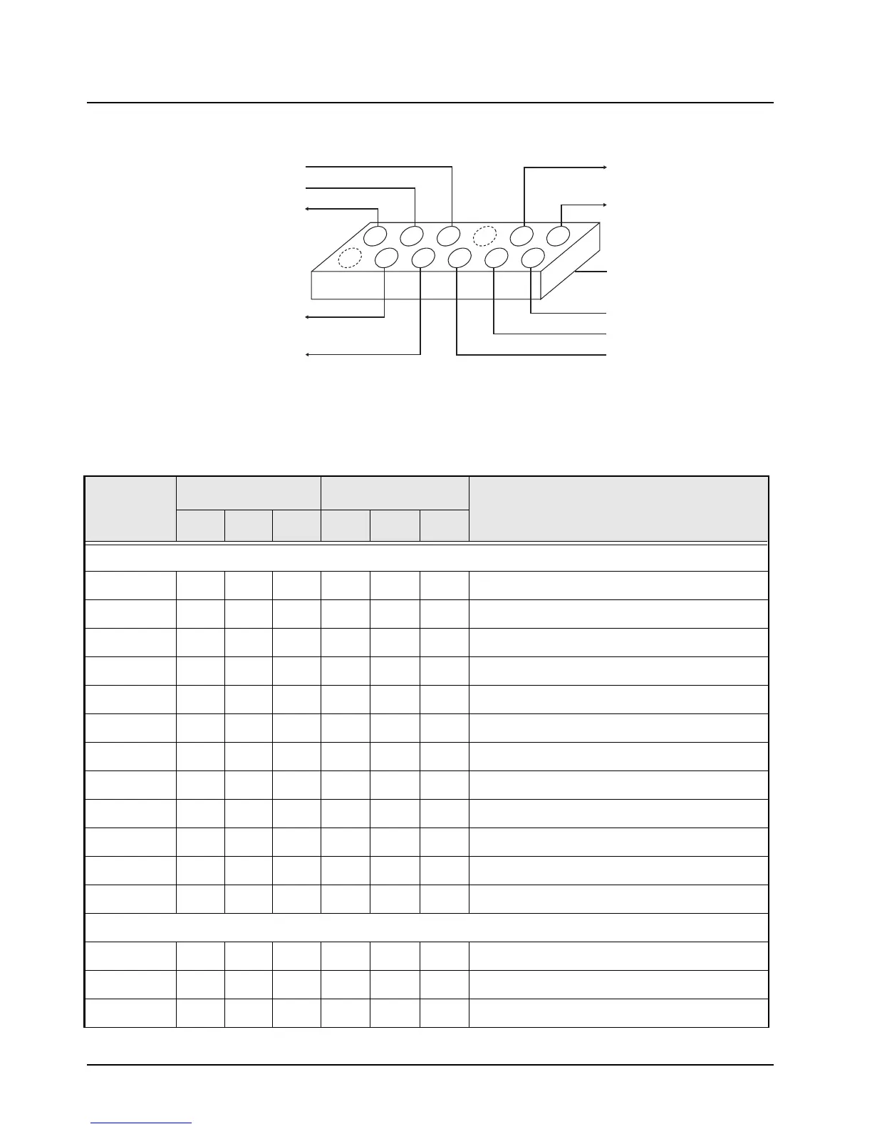
Figure 4-6. PA Test Adapter, 50 Watt Power Amplifier
Table 4-15. Power Control DC Voltage Chart
LOCATION
RX MODE TX MODE
COMMENTS
LOW TYP HI LOW TYP HI
P0853
1 ––––––
Key (no pin or wire)
2002.03.2
Control Voltage Limit
3 0 2.0 7.0 9.2
Control Drive Voltage
4 10.8 13.8 16.6 10.4 13.4 16.2
Current Sense +
5 0 0 0 9.2 9.4 9.8
Keyed 9.4
6 10.8 13.8 16.6 10.4 13.4 16.2
A+ to Command Board
70 1.2
Temp Sense (cutback begins at 3.3 V)
8 ––––– v
Key (no pin)
9 0 1.5 3.5 5.0
Forward Detect Volt
10 10.8 13.8 16.6 10.4 13.4 16.2
A+ to Command Board
11 9.4 9.6 9.9 9.4 9.6 9.9
9.6-V Supply from Command Board
12 10.8 9.8 13.1 15.9
Current Sense – (voltage delta 150 mV)
U0500
1 000000
Ground
20 3.2
Control AMP Input
3 000000
Control AMP Input (not used)
A+ TO COMMAND BOARD
CURRENT SENSE +
A+ TO COMMAND BOARD
CURRENT SENSE -
CONTROL VOLTAGE LIMIT
CONTROL VOLTAGE DRIVE
K9.4
FEMALE RECEPTACLE
CONNECTOR W 100 MIL
SPACING MATES TO P853
REGULATED 9.6V
V DETECT
TEMP SENSE
8
6
4
2
10
12
7
5
3
1
9
11
 Loading...


