6881076C25-E September 5, 2008
Troubleshooting Procedures: Power Amplifier Procedures 4-67
4.5.3.1.2 PA Functional Testing
To test the PA assembly for proper operation, perform the following steps:
NOTE: The following instructions pertain to both the 15 Watt and 35 Watt power amplifiers. A
distinction between the two PA’s is given only where necessary.
1. Disassemble the PA assembly from the radio, leaving the power cable connected to the rear
connector. Replace the 15-Watt PA shield (or the 35-Watt PA shield and cover). Disconnect
the coax connectors and the ribbon cable. Connect a power meter to the antenna port using
minimum cable length.
When setting or measuring RF power at 800 MHz, follow these guidelines to avoid
measurement errors due to cable losses or non-50-ohm connector VSWR:
- All cables should be very short and have Teflon dielectric.
- Attenuators and 50-ohm loads should have at least 25 dB return loss.
- Mini UHF to 'N' adapter P/N 5880367B21, should be used at the antenna connector. All
other connectors should be 'N' type. No other adapters, barrel connectors, etc. should be
used.
Maximum input level to the PA is 200 mW. Over driving the buffer could result in damage to
the PA buffer stage.
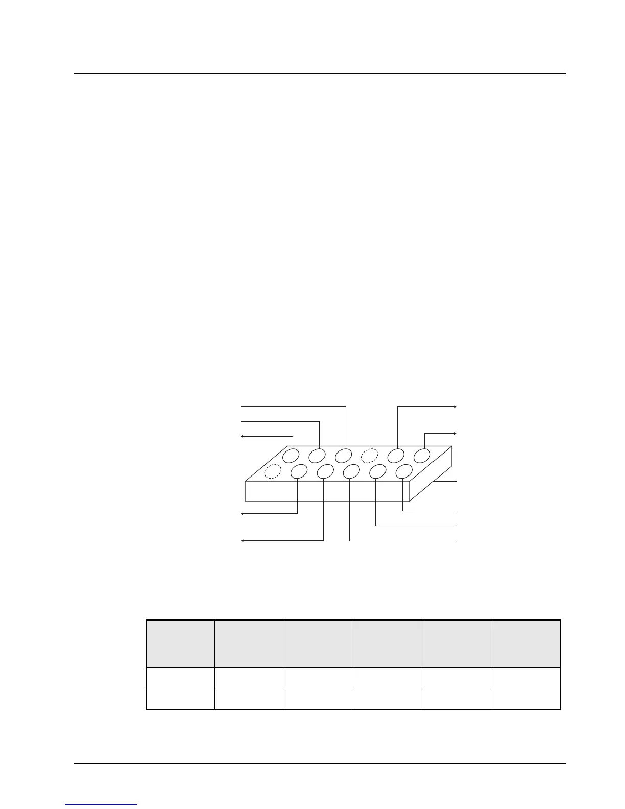
2. Apply the input power and DC voltages indicated in Table 4-23 to the power amplifier
assembly. To make the DC connections, use small spring-clips or make a test adapter similar
to that shown in Figure 4-10.
Figure 4-10. PA Test Adapter, 15 and 35 Watt Power Amplifier
Table 4-23. DC Voltages and Input Power Chart
Test Keyed 9.4 V 9.6 V
CONTROL
VOLTAGE
DRIVE
POWER IN
(mW)
A+
(V)
Transmit 9.4 9.6 See note
a
a. Set initially to zero. Increase value until power equals 17 watts(15-Watt radio) or 38 Watts
(35-Watt radio) or 11.0 V maximum.
0.1 13.0
Receive 0 9.6 0 0 13.0
A+ TO COMMAND BOARD
CURRENT SENSE +
A+ TO COMMAND BOARD
CURRENT SENSE -
CONTROL VOLTAGE LIMIT
CONTROL VOLTAGE DRIVE
K9.4
FEMALE RECEPTACLE
CONNECTOR W 100 MIL
SPACING MATES TO P853
REGULATED 9.6V
V DETECT
TEMP SENSE
8
6
4
2
10
12
7
5
3
1
9
11

 Loading...


