September 5, 2008 6881076C25-E
3-18 Theory of Operation: ASTRO Spectra VOCON Board
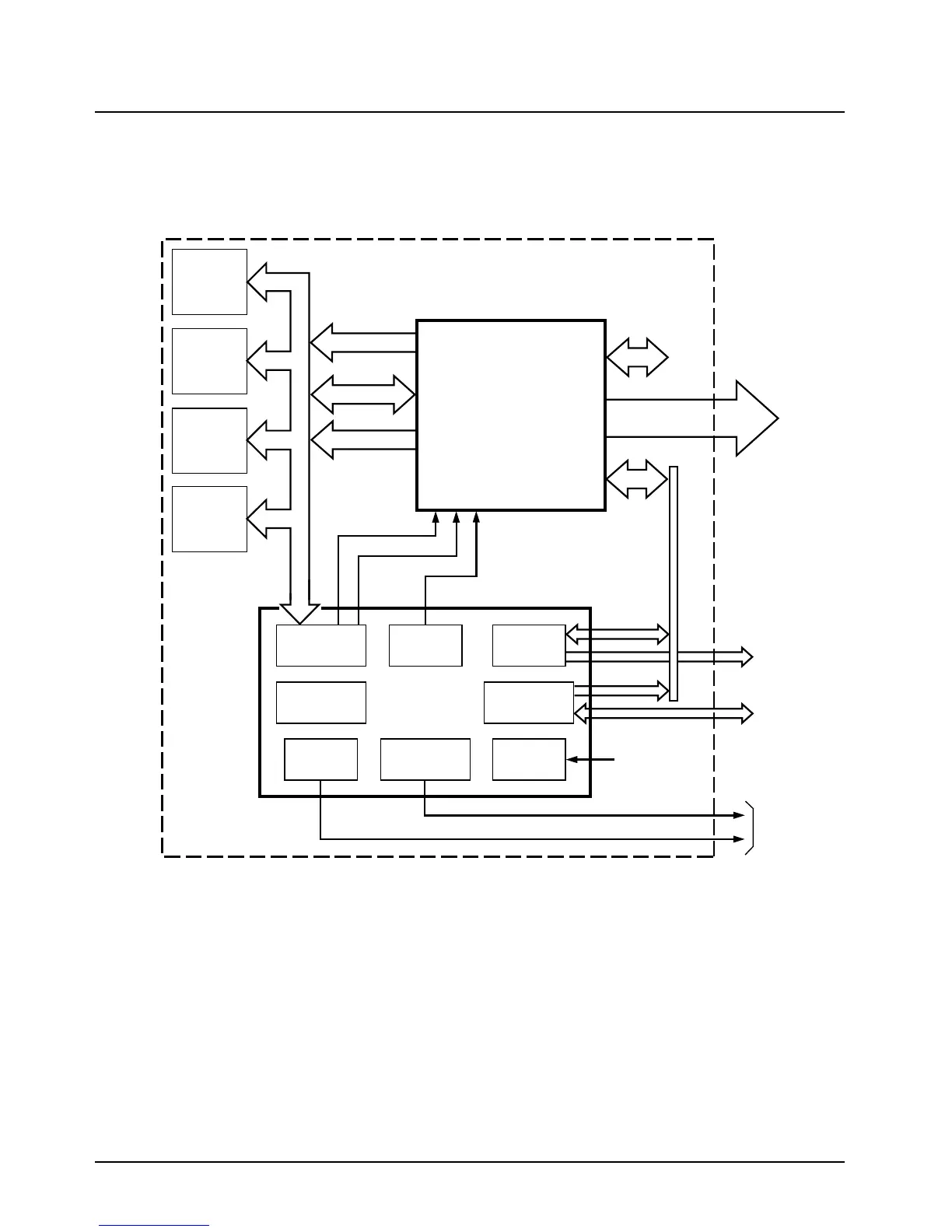
When transmitting, the microphone audio is passed from the command board to the ADSIC, which
incorporates an analog-to-digital (A/D) converter to translate the analog waveform to a series of
data. The data is available to the DSP through the ADSIC parallel registers. In the converse way, the
DSP writes speaker data samples to a D/A in the ADSIC, which provides an analog speaker audio
signal to the audio power amplifier on the command board.
Figure 3-8. VOCON Board – Vocoder Section
3.3.4 RX Signal Path
The vocoder processes all received signals digitally. This requires a unique back end from a
standard analog radio. This unique functionality is provided by the ABACUS II IC with the ADSIC
(U406) acting as the interface to the DSP. The ABACUS II IC located on the RF board provides a
digital back-end for the receiver section. It provides a digital output of I (In phase) and Q
(Quadrature) data words at 20 kHz sampling rate through the ADSIC interface to the DSP. Refer to
the appropriate transceiver section for details on ABACUS II operation.
The ADSIC interface to the ABACUS II is comprised of the four signals SBI, DIN, DIN*, and ODC
(refer to Figure 3-9 on page 3-19).
SSI
SERIAL
EXTAL
MODB
MODA
HC11/DSP
Interface
D0-D23
BUS
CONTROL
A0-A15
U405
DSP56001
SCI
SERIAL
Encryption
Interface
Host
Port
System
Clock
Gata Array
Logic
ABACUS Rx
Interface
Tx D/A
General
Purpose I/O
Speaker
D/A
Microphone
A/D
Serial
Config.
U406
ADSIC
ABACUS
Interface
Modulation
Out
Command
Board
U414
8Kx24
SRAM
U404
256Kx8
FLASH
U403
8Kx24
SRAM
U402
8Kx24
SRAM
HC11
SPI
MAEPF-25106-O

 Loading...


