September 5, 2008 6881076C25-E
2-10 General Overview: Radio Power
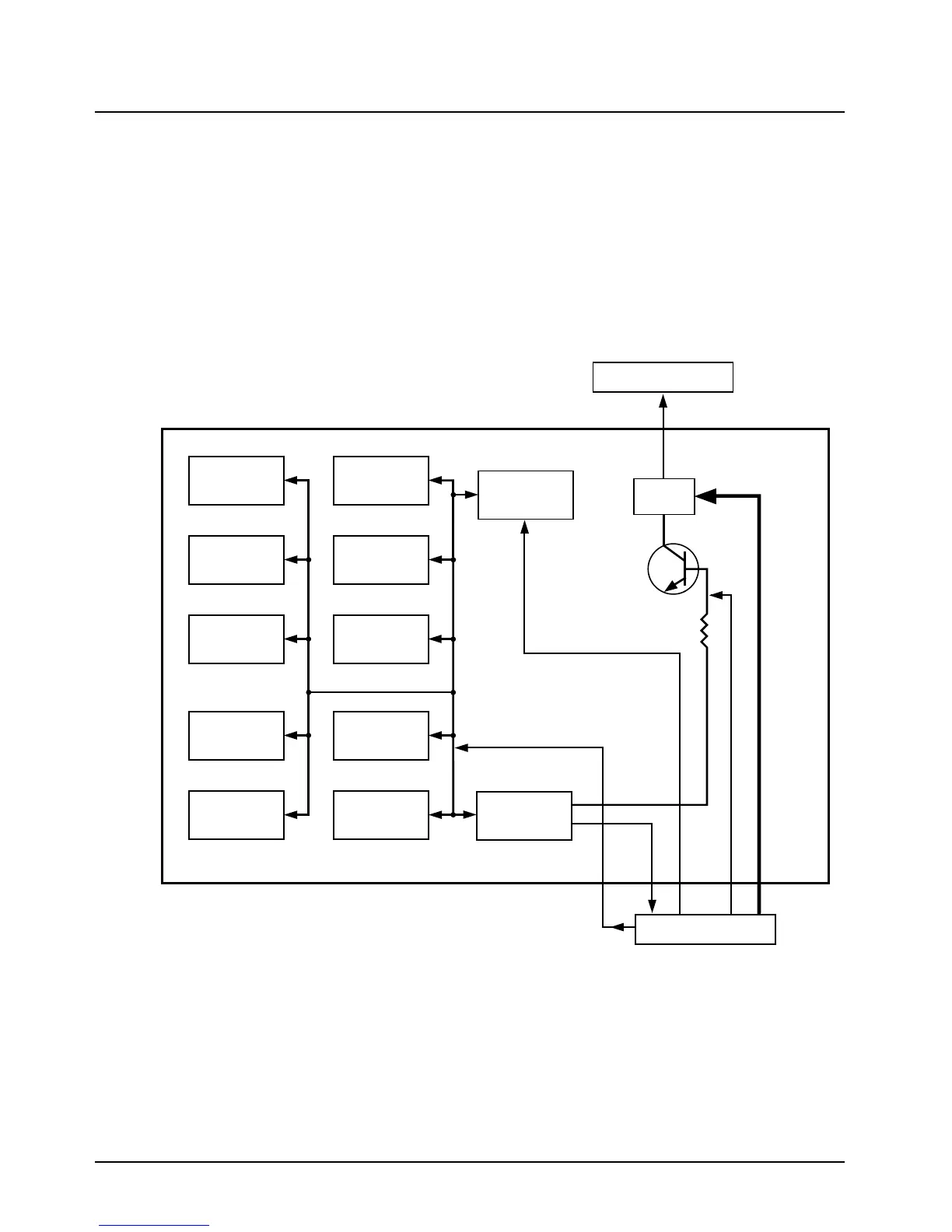
Transistor Q206 controls solid-state power switch Q207, providing SWB+ to the encryption module
(if equipped). The "SWB+" and "UNSWB+" encryption voltages both originate from pin 38 of J501
and are fed to the encryption module via J801.
Port PL3 (5-V EN) on the SLIC and Q207 are under the control of the microcontroller unit (MCU),
U204. This allows the MCU to follow an orderly power-down sequence when it senses that the B+
sense is off. This sense is provided via resistor network R222 and R223, which provides an input to
the A/D port to the MCU.
It should also be noted that a system reset is provided by the undervoltage detector, U407. This
device brings the system out of reset on power-up, and provides a system reset to the
microcomputer on power-down.
Figure 2-2. ASTRO Spectra B+ Routing for Vocoder/Controller (VOCON) Board
ADSIC
U406
DSP56001
U405
256Kx8
FLASH
U404
8Kx24
SRAM
U402
SRAM
U202
EEPROM
U201
SLIC IV
U206
Switch
Q207
5V Analog
5V Digital
B+_CNTL
B+_Sense
B+_
Sense
Vocoder/Controller
UNSW_B+
J501
8Kx24
SRAM
U403
8Kx24
SRAM
U414
256Kx8
FLASH
U205
256Kx8
FLASH
U210
J801
MAEPF-25104-O
HC11F1
MCU
U204
SW B+
5V EN

 Loading...


