Controls and Indicators Interface
46 Module Hardware Description January 1, 2006
Wake-Up Out
Some applications incorporate their own power saving mode, in which they operate with minimal
functionality, including disabling of interfaces and serial communications.
The G24 supports a low power mode feature in the host application. The wake-up-out
(WKUPO_N) output signal is designed for this feature. This signal is used by G24 to indicate that
it requires to communicate with the host application, due to an incoming call or data, or an
unsolicited event.
Applications that incorporate a low power mode should use this signal as an indication to switch
from low power mode to normal operation. The application should not switch to low power mode
while the WKUPO_N signal is enabled (low).
When G24 has completed the current communications exchange with the host application, it will
switch the WKUPO_N signal to high, indicating to the application that it may return to low
power mode.
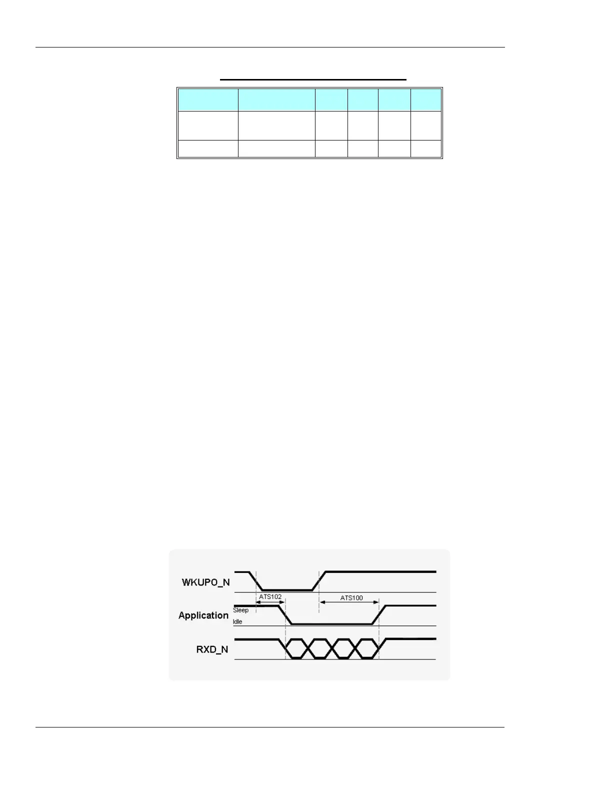
The host application wakeup mechanism, using the WKUPO_N signal, is controlled by 2 AT
commands (see Figure 2-27):
• ATS102 - Defines the delay time in milliseconds that G24 will wait, after asserting the
WKUPO_N signal, before sending data on the serial interface. This delay is required to allow
the application enough time to reactivate from low power mode and switch to normal mode.
If ATS102=0, which is the default value, the WKUPO_N signal and mechanism is disabled.
• ATS100 - Defines the application minimal wakeup duration, in milliseconds, for a single
wakeup event. This time definition is required to avoid frequent unnecessary wakeup events
and consequent ATS102 delays.
This AT command is relevant only if ATS102 > 0, which enables the WKUPO_N signal
operation.
Figure 2-27: WKUPO_N Operation
Line regula-
tion
5mV
PSRR 20 Hz - 20 kHz 60 dB
Table 2-21: VREF Specifications (Cont.)
Parameter Conditions Min Typ Max Unit

 Loading...