Do you have a question about the Motorola ACE3600 RTU and is the answer not in the manual?
Brand | Motorola |
---|---|
Model | ACE3600 RTU |
Category | Control Unit |
Language | English |
Introduces the ACE3600 as a programmable Remote Terminal Unit (RTU) for automation tasks and its role in monitoring and control.
Highlights the advantages of ACE3600, combining legacy features with modern technologies like a powerful CPU and real-time OS.
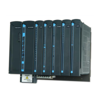
Details the various structures and frame components of the ACE3600 RTU, including chassis, slots, and backplane.
Lists and describes the essential components of the ACE3600 RTU, such as power supply, CPU, I/O modules, and terminal blocks.
Provides essential safety guidelines and information regarding RF exposure for ACE3600 RTU models with radios.
Provides general information, warnings, and installation codes for setting up the ACE3600 RTU.
Details the procedure and dimensions for mounting the ACE3600 frame on a wall, including chassis variations.
Explains how to install the ACE3600 frame into a standard 19" rack unit using provided brackets and screws.
Covers the essential procedures for making secure power and ground connections to the ACE3600 RTU, including warnings.
Describes the necessary steps to properly connect I/O modules to ground for safe and correct operation.
Provides a general overview of the ACE3600 power supply module, its function, and available options.
Details the input and output connectors on the power supply module's front panel, including auxiliary outputs and power inputs.
Explains the ACE3600 backup battery, its capacities, and how it interacts with the power supply module.
Provides a step-by-step procedure for safely replacing the lead-acid backup battery in the ACE3600 RTU.
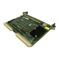
Describes the ACE3600 CPU module as the main element, controlling I/Os, processing data, and communicating with the outside world.
Details the communication ports available on the ACE3600 CPU front panel, including USB, Serial, and Ethernet.
Outlines the CPU memory components: Flash, SDRAM, and optional SRAM Plug-in, and their respective storage functions.
Details the behavior and meaning of the various LEDs on the CPU module, indicating status, communication, and application activity.