Mixed Analog Module
15-2
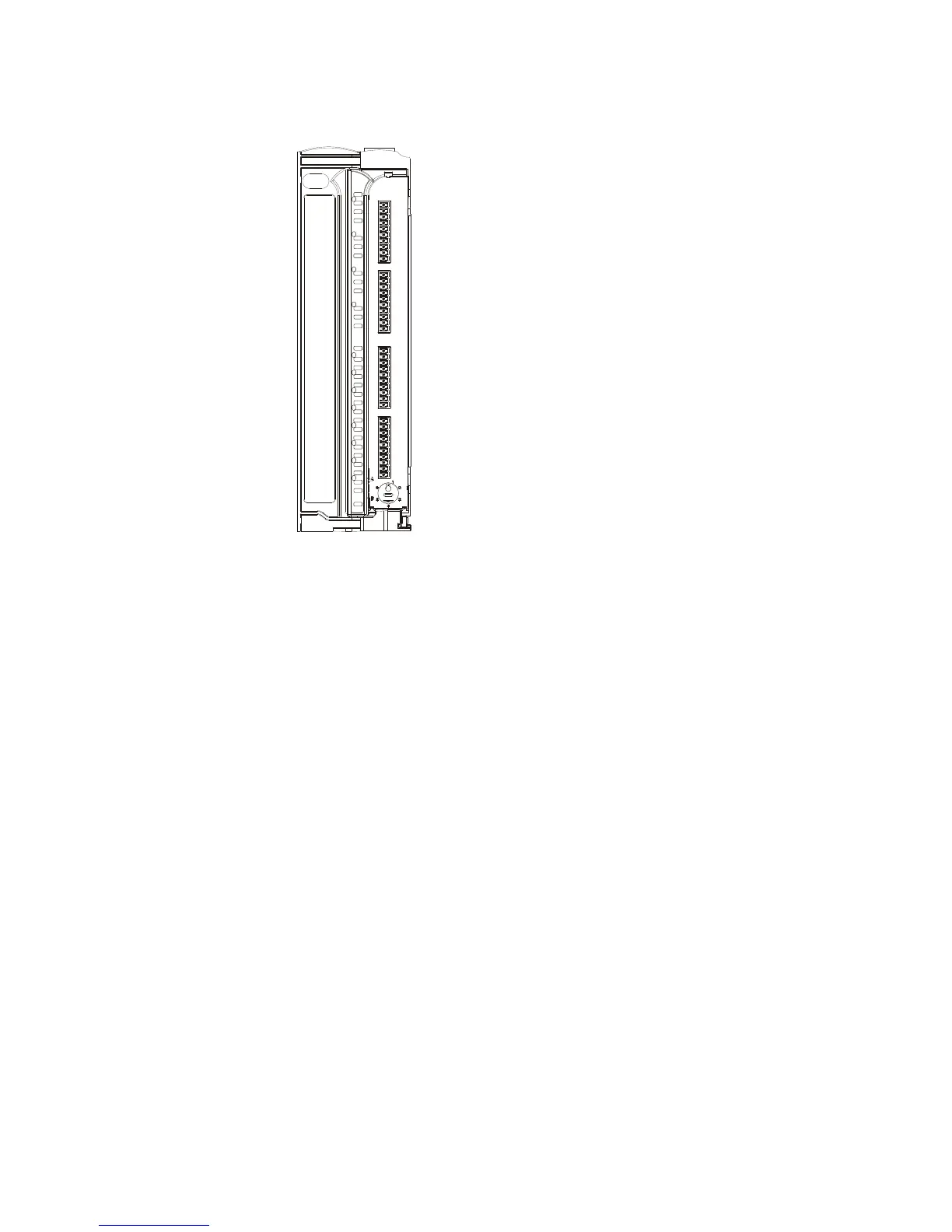
Figure 15-2 provides a detailed view of the Mixed Analog module front panel.
ERR
Iout
Vout
CAL
24V
OF
UF
OF
UF
OF
UF
OF
UF
OF
UF
OF
UF
OF
UF
OF
UF
1
2
3
4
1
2
3
4
5
6
7
8
24V
Iout
Vout
CAL
Iout
Vout
CAL
Iout
Vout
CAL
Figure 15-2 ACE3600 Mixed Analog Module – Front Panel
For a description of the AIs in the Mixed Analog modules, see the Analog Input Module
chapter. For a description of the AOs in the Mixed Analog modules, see the Analog Output
Module chapter.
The Mixed Analog modules support an optional 24V DC floating plug-in power supply to
power external devices.
For a description of I/O module construction, location, LEDs, TB holder, and other common
I/O module features, see the I/O Modules chapter above. For details on Mixed Analog Module
specific parameters and configuration, see the Mixed Analog Module Configuration section
below.
Mixed Analog Module Configuration
For configuration of the AIs, refer to the AI Module chapter.
For configuration of the AOs, refer to the AO Module chapter.
Sleep Mode
Each Mixed Analog module can be switched by the user application program to Sleep Mode.
In Sleep Mode, the module does not function and the power consumption is minimized. During
Sleep mode the user application program will get/set the predefined values per each I/O.

 Loading...


