Digital Output/Digital Input FET Module
8-5
shows the actual value of each input and output. It is also possible to change the input filter
setup for the duration of the Hardware test and change the value of the DOs.
In the Hardware Test utility, it is possible to set the module to Freeze Mode. In this mode the
user application program will get the KLV/PDV of each input in the module instead of the
actual input value. The DO values will keep the last value they had when the module was
switched to Freeze Mode. Freeze mode enables testing the inputs and outputs while the user
application program is running.
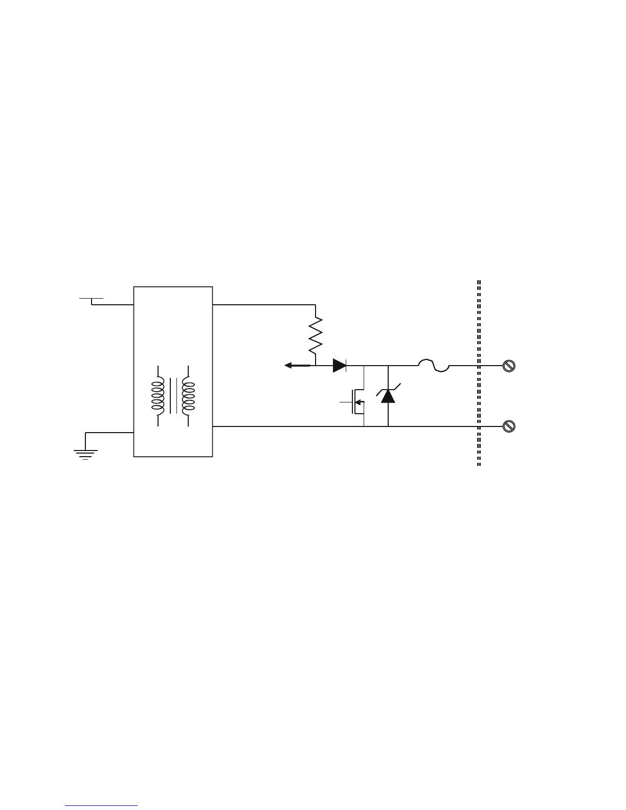
I/O Circuit Diagram
COM
DO/DI
Floating
Voltage
Converter
DI Status/
DO Back
Indication
DO
Control
* FET Always “OFF” in DI configuration
*
Self Recovery Fuse
1A
5V
33V
12V
DO/DI - Typical I/O Circuit
“ ”
20KΩ
12V

 Loading...


