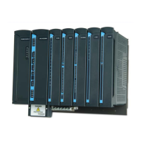
CPU Module
4-12
CPU LEDs Behavior
The table below describes the behavior of the LEDs on the CPU module.
Table 4-4 ACE3600 CPU LEDs Behavior
LED Name Description Status
PWR Power LED
Bicolor LED (Red, Green)
Flashing Red – Power exists; CPU FPGA not
loaded.
Green – Power exists; CPU is running from a
recognized power supply (one of the six
power supply options.)
Red – Failure on power-up. CPU is running
from an unrecognized power supply.
ERR Error Logger Status LED
Bicolor LED (Red, Green)
OFF – No new errors or warnings.
Green – New message logged.
Orange – New warning logged.
Red – New error logged.
Note: In systems with I/O expansion, the ERR
LED can indicate an error in either the main
or expansion frame.
RST Reset LED
Bicolor LED (Red, Green)
Green – On startup
OFF – Successful power-up or restart.
Red – Power-up or restart failed.
APPL Application LED
Bicolor LED (Red, Green)
OFF – No user application program in the
Flash memory.
Green – User application program is running.
Orange – User application program was
paused by user (during Hardware Test.)
CONF Configuration LED
Bicolor LED (Red, Green)
OFF – Configuration was not loaded.
Green – Configuration was loaded.
Red – Configuration error.
H1 LNK1
*
USB Host1 LNK (link)
Green LED
ON – A USB device is connected.
OFF – No link exists between the CPU and
the MotoTrbo radio.
*
The LED names I1 ACTV, I1 L/RX, H1 LNK1/LNK2, and D1 RX appear only in CPU 3680.

 Loading...