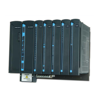
Digital Output/Digital Input FET Module
8-4
Table 8-1 ACE3600 DO/DI FET Module Configurable Features
Parameter Selection Default Setup Per Module/
Input
Parameter
Setup Location
DI Fast Capture Disabled
/Enabled
Disabled Input RTU
configuration
DI Filter 0-254 (x 0.2 mS) 50 * 0.2 mS
(=10 mS)
Module RTU
configuration;
‘C’ Program
DI Counter
Filter
0-255 (x 0.05 mS) 20 * 0.2 mS
(= 1 ms)
Module RTU
configuration;
‘C’ Program
DI Event Time
Tagging
Disabled
/Enabled
Disabled Input Application
Programmer I/O
link table
DI Keep Last
Value &
Predefined
Value
KLV/PDV
PDV = 0/1
KLV Input Application
Programmer I/O
link table
DI Mask No /Yes No Input Application
Programmer I/O
link table
DO Keep Last
Value &
Predefined
Value
KLV/PDV
PDV = 0/1
KLV Output Application
Programmer I/O
link table
DO Mask No /Yes No Output Application
Programmer I/O
link table
Sleep Mode
Each DO/DI module can be switched by the user application program to Sleep Mode. In Sleep
Mode, the module does not function and the power consumption is minimized. During Sleep
mode, the user application program will get the KLV or PDV per each DI.
Module Status and Diagnostics
In the event of a DO/DI module failure, the ERR LED on the module will be lit. This event is
registered by the CPU in the Error Logger. DO/DI module failure status is also visible to the
user application program.
The DO/DI module can be diagnosed and monitored using the STS Hardware Test utility. The
Hardware Test verifies that the module is operational, presents the module configuration and

 Loading...