Installation
2-21
4) Repeat steps 1-3 for the PGND wires on all I/O modules.
Connecting an RTU to Ground
When an RTU is installed, individual ground wires (from the power cable and from the PGND
pin on the I/O module cables) are connected to the grounding strip on the chassis. The
grounding strip must then be connected to the grounding point of the cabinet or 19" rack.
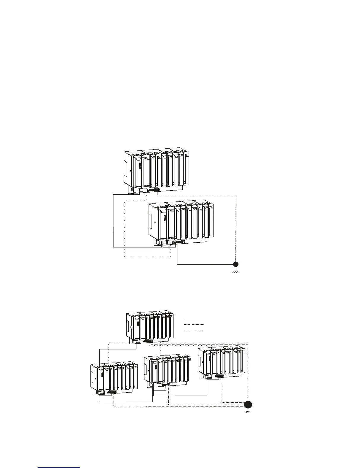
In an RTU with I/O expansion, the grounding strip of each frame must be connected to the
grounding point of the cabinet or 19" rack. Figure 2-23 below depicts the ground connections
of an RTU with a single expansion frame and Figure 2-24 depicts the ground connections of an
RTU with multiple expansion frames.
Crossed
LAN Cable
I/O Frame
DC
Cable
Main Frame
Grounding
Wire
Protective Ground
Figure 2-23 Ground Connections of an RTU with a Single Expansion Frame
I/O Frame #3
Main Frame
Protective Ground
I/O Frame#1
I/O Frame #2
Ground Wire
Expansion
Power Cable
LAN Cable
Figure 2-24 Ground Connections of an RTU with Multiple Expansion Frames

 Loading...


