10
English
English
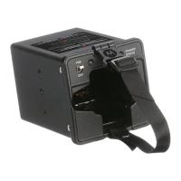
Step 5:
Turn the unit around and plug each LCD module/
wire connector into its corresponding PC board.
The connector and header are keyed (grooved to
properly align during insertion.)
Communication Harness
(to DB15 Connector)
LCD Module/Wire
Connector
CDM_Install - B.fm Page 10 Monday, February 10, 2003 2:51 PM

 Loading...