The filtered RF signal is then applied to the RF input
of a broadband mixer IC. An injection signal (FIRST
LO), supplied by the FGU, is applied to the second input
of the mixer stage. The resulting difference frequency
(44.85MHz for VHF and 73.35MHz for UHF), is the first
IF frequency. The first IF frequency is then filtered by a
2-pole crystal filter to remove unwanted mixer products
and routed to the IF IC.
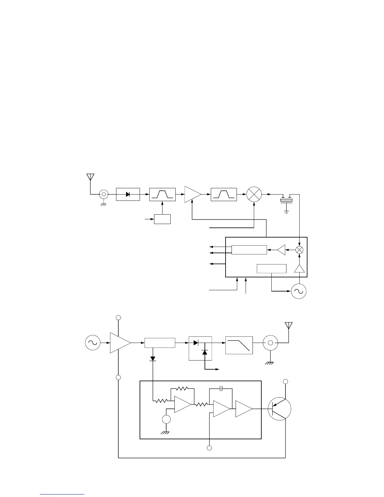
D. Receiver Back End (See Figure 3)
In the IF IC, the first IF frequency is down convert-
ed, amplified, filtered, and demodulated to produce the
recovered audio. The IF IC is electronically pro-
grammable, and the amount of filtering, which is
dependent on the radio channel spacing, is controlled
by the microcomputer. Additional filtering, which used to
be provided externally by a conventional ceramic filter,
is replaced by internal filters in the IF IC. The IF IC uses
a type of direct conversion process where the second
LO frequency is very close to the first IF frequency. The
IF IC controls the second LO VCO and causes the VCO
to track the first IF frequency, producing a phase-locked
operation. The IF IC also provides a recovered signal-
strength indicator (RSSI) and squelch output for use in
other parts of the radio.
E. Transmitter (See Figure 4)
The transmitter consists of the following stages:
• Harmonic Filter
• RF Power Amplifier
• ALC IC, which controls the power output
Harmonics of the carrier frequency are generated
by the PA module and antenna switch. The harmonic fil-
ter circuit attenuates the unwanted signals.
5
 Loading...


