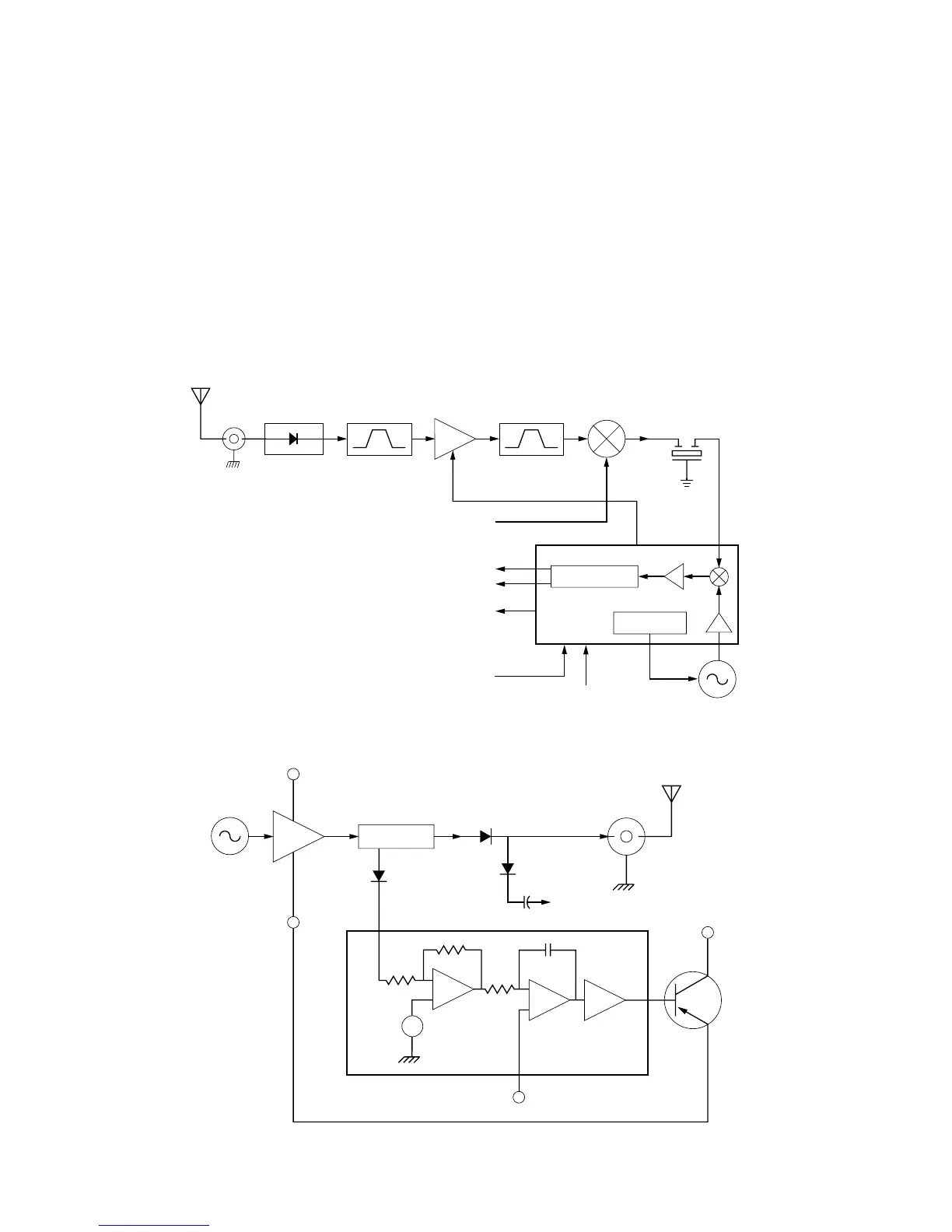
D. Receiver Back End (See Figure 6)
In the IF IC, the first IF frequency is down convert-
ed, amplified, filtered, and demodulated to produce the
recovered audio. The IF IC is electronically pro-
grammable, and the amount of filtering, which is
dependent on the radio channel spacing, is controlled
by the microprocessor. Filtering is accomplished by
internal filters in the IF IC. The IF IC uses a type of
direct conversion process where the second LO fre-
quency is very close to the first IF frequency. The IF IC
controls the second LO VCO and causes the VCO to
track the first IF frequency, producing a phase-locked
operation. The IF IC also provides a recovered signal-
strength indicator (RSSI) and squelch output for use in
other parts of the radio.
E. Transmitter (See Figure 7)
The transmitter consists of the following stages:
• Low-pass antenna matching circuit
• RF Power Amplifier
• ALC IC and coupler, for power output control
The low-pass antenna matching circuit attenuates
RF PA harmonics, and provides the optimum phase
load to the RF PA. The RF PA module is a multi-stage
amplifier, which has the required gain to produce an out-
put level of several watts. Some harmonic filtering is
also accomplished in the RF PA.
Power control is achieved by using the coupler
detector to feed back a portion of the PA output to the
ALC circuit. This ALC circuit increases or decreases the
7
 Loading...


