overall PA gain as appropriate. Another function of the
detector is to provide a signal when the VSWR exceeds
the threshold level. This signal, combined with the
forward detected power, is used to reduce the PA output
power, thus protecting the PA under high VSWR
conditions.
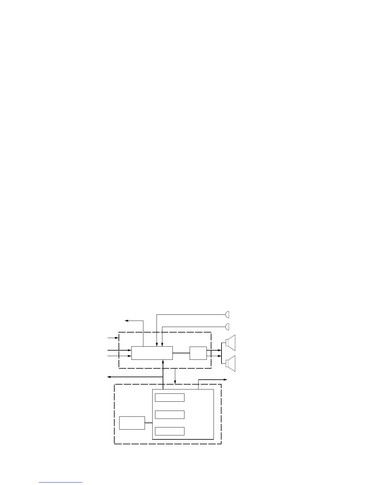
V. CLOSED ARCHITECTURE CONTROLLER
A. General (See Figure 8)
The controller board is the central interface between
various subsystems of the radio. It is segregated into
digital and audio architecture. The digital portion con-
sists of a special Motorola microcomputer. The audio
power amplifier (AUDIO PA) and audio/signalling/filter
IC (ASF IC) form the backbone of the audio/signalling
architecture. The controller board has its own voltage
regulators to generate 5 volts, sourced by switched B+
from the battery.
B. Digital Architecture
The Motorola microcomputer consists of 640 bytes
of EEPROM, 760 bytes of RAM, and 24k of ROM. The
microcomputer executes the radio software and moni-
tors the activity of all user interfaces. Using the
communication buses, the microcomputer handles the
responsibility of programming all applicable ICs in the
radio, including those on the RF transceiver board. This
programming sets up the ICs to properly perform a vari-
ety of functions, such as what frequency to transmit or
what channels to scan. The digital circuitry is powered
by a discrete 5-volt regulator to help isolate the digital
signals from the audio signals in nearby circuits.
C. Audio Signalling Architecture
A Motorola custom IC (ASF) provides both transmit
and receive audio and signalling processing. The ASF
IC is programmable by the microcomputer via the serial
peripheral interface (SPI). It provides filtering on both
transmit and receive audio, and also provides PL, DPL,
and MDC encoding and decoding.
In the transmit mode, the ASF IC amplifies, shapes,
limits, and filters the outgoing signal. The processed sig-
nal is sent to the transceiver board’s FGU. In the receive
mode, the demodulated signal from the receiver back
end is amplified, filtered and routed to the AUDIO PA for
amplification. The ASF IC provides pre-emphasis and
de-emphasis as well as squelch. Based on a reference
signal from the transceiver board, the ASF IC provides
the microcomputer with a clock signal.
Received audio signal amplification is achieved by
the AUDIO PA IC. The IC’s output drives the radio’s
internal speaker, or an external speaker connected via
an option cable. In order to minimize the effects, and to
further isolate the audio signals from the digital signals,
the audio section has its own isolated 5V regulator on
the AUDIO PA.
VI. OPEN ARCHITECTURE CONTROLLER
A. General (See Figure 9)
The controller board is the central interface between
various subsystems of the radio. The controller board is
composed of both digital and audio circuits. The digital
portion consists of a special Motorola microprocessor
(U705), a custom, gate-array, memory-support-logic IC
(SLIC), U710, and the memory devices (U713, U714,
and U715). The audio circuits include the audio power
amplifier (U702), the audio/signalling/filter IC (ASF IC),
U701, and in the 900MHz radios, the Hear Clear IC,
U601. The controller board has its own voltage regula-
tors to generate 5 volts, sourced by switched B+ from
the battery. The open architecture controller board also
has a plug-in interface for secure voice encryption
options, and another interface for the display and key-
pad version radios.
8
 Loading...


