48
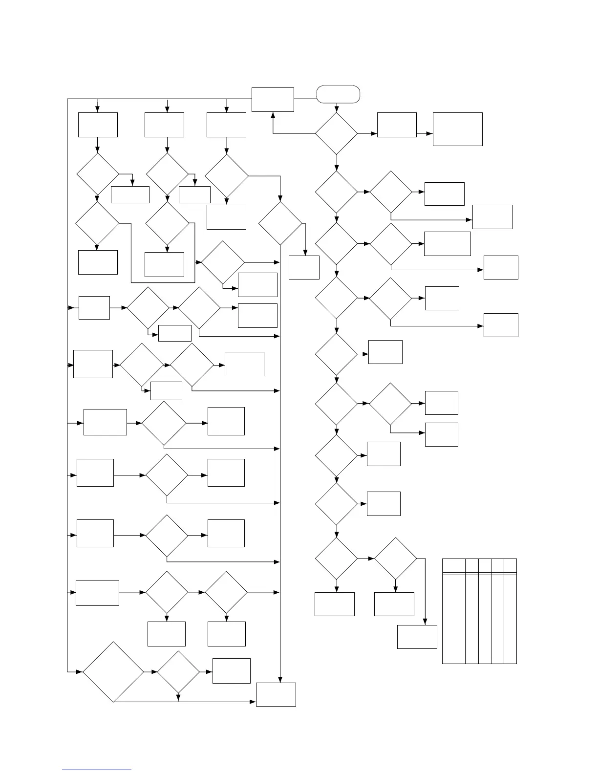
TROUBLESHOOTING FLOW CHART #8A
(Closed Architecture Controller)
Closed Controller
Check
Power Up
Alert Tone
OK?
Note 1.
Radio Button
functions and
Signalling
Problems.
Not able to
program RF
Board ICs
Before replacing
MCU, check MCU
voltages and check
for I/O activities.
U705
Pin 77
EXTAL =
7.9488 MHz
?
Read
Radio
OK?
Check setup and
check J701,
voltages at pins
22, 26.
Reprogram the
correct data.
Note 2.
See FGU
Troubleshooting
Chart #4A
Check
C774
Check
J704
Pin 13 =
2.1/2.4
MHz
U701
Pin 33 =
2.1/2.4
MHz
5V at
U709
Pin 1
?
7.5V at
U709
Pin 8
?
Check Vol
SW, Fuse and
Battery.
Replace
U709
Check R717
pin 5 of U709
pin 24 of U701
C708
U705
pin 79
High
?
Replace
Q702
5V at
collector
Q702
?
6.8V at
base of
Q702
?
Replace
Q705
Check
R731
U705 pin
80 MOD _B
high
?
Check
R730
U705 pin
81 MOD _A
High?
OFF Radio
& Power Up.
Any data on
U705
pin 83?
U701
pin 35 =
3.6864 MHz
?
Replace
U701
Change
U701
Replace
U705
Replace
U705
MCU is
OK
Check R708,
R709, C730
U705
pin
48 > 3.8
?
Check
J01-10, 18
voltage
ext. spk.
Check
J701-10, 18
voltage
ext. mic.
Check
J710, R711
J703-7voltage
mode SW.
Check
J703-12, 13,
14, 15 voltage
chan. SW
Check
J703-3
voltage
RAT SW
Replace
Faulty
Component
Replace
Speaker
Speaker
OK
?
LED U704
R719
OK
?
Check
J703-2
Voltage
MON. SW
Press MON
Button U705
pin 59 low
?
Press MON.
Button, Radio
does not
respond.
MONITORPTT
Press PTT.
Red LED
does not
light up.
Press PTT,
U705 Pin 61
Low?
PTT
J704-4
HIGH?
See FGU
Troubleshooting
Chart #4A
Enable &
Press RAT
Button.
U705 pin 65
low?
U705 pins
40, 41,
42, 43
status as
Table 1?
Reprogram
Radio
Info. with
RSS
Correct
?
U705 pin 50
POSA = 0V
POSB = 2.5V
POSC = 5V
?
Ext
PTT U705
Pin 37, 38
low
?
U705
pin 38 = low
pin 37 = high
?
Read
radio
low batt.
threshold
info. ok?
Reprogram
the correct
threshold
voltage.
Pulse
train
appear at
U705 pin 9
?
Switch to PL Mode
and MDC SEL CALL
option enabled.
Pulse train at
U705 pin 6
?
Enable low
battery alert.
Alert at nominal
battery voltage.
Radio has no
ext. audio
Radio could
not PTT
externally.
Flip the toggle
switch. Radio not
function as
programmed.
Turn channel
switch sequence
RX freq. not as
program.
Check
J703-18
Voltage.
EMER. SW
Press
EMER
Button
U705 pin 62
low?
See PTT
Troubleshooting
PTT
OK?
EMER
Enable and
press EMER.
Button. Red LED
does not blink.
RAT
CHANNEL
SW
3-POSITION
SW
EXT
PTT
EXT
SPK
LOW
BATTERY
PL & MDC
SIGNALLING
CHANNELPIN
40
PIN
41
PIN
42
PIN
43
1
2
3
4
5
6
7
8
9
10
11
12
13
14
15
16
1
1
1
1
1
1
1
1
0
0
0
0
0
0
0
0
1
1
1
1
0
0
0
0
1
1
1
1
0
0
0
0
1
1
0
0
1
1
0
0
1
1
0
0
1
1
0
0
1
0
1
0
1
0
1
0
1
0
1
0
1
0
1
0
NOTE 1:If Power Alert is Enabled:
300Hz Tone - Micro-P Fail Self Test
300Hz Tone - Micro-P Fail Self Test
900Hz Tone - Micro-P Pass Self Test
No Tone - Micro-P is not running normally.
NOTE 2:Wrong Codeplug Data could cause radio failure.
Table 1
YES YES
YES NO
YES
NO
YES
NO
NO
NO
NO NO
YES
YES
YES
NO
YES
NO
YES
YES NO
NO
YES
NO
YES
NO
YES
NO
YES
YESYES
NONO
NO NO
YESYES
YES
YES
NO
NO
YES
NO
NO
YES
NO
YES
YES
NO
YES
NO
NO
YES
YES
YESYES
YES
YES
NO
NO
NO
YES
MAEPF-23278-O
Check U703-1
Voltage PTT
SW
Can
radio
key up
?
Go to PTT
Enable and
Press RAT.
LED does not
Blink
NO
NO
 Loading...


