Accessory Connections 13
Chapter 6
Accessory Connections
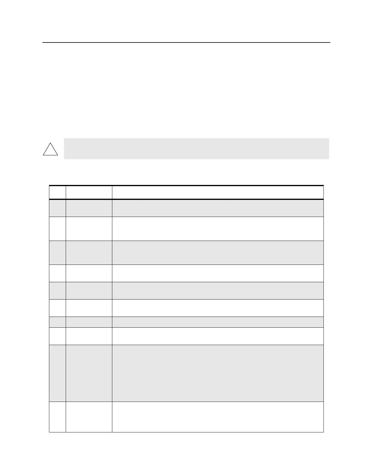
6.1 Accessory Connector Pin Functions
This section gives a description of the accessory connector pin functions.
CAUTION: The accessory connections shown are not compatible to some other models of Motorola radios.
Check the appropriate accessory or technical manual for further information.
Table 6-1: Connector Pin Functions
Pin Function Description
1 External
Speaker (-)
Connect external 8 or 4 Ohm speaker to pins 1 and 16.
CAUTION: Bridge-type output. Neither pin 1 nor 16 is Ground.
2 External Mic
Audio
Input impedance: 500 Ohms.
80 mV rms at 1 kHz for 60% deviation.
This path is enabled when external mic PTT is keyed.
3 External Mic
PTT
Put this pin low (less than 0.66 V dc) to key transmitter and enable external mic audio
path. This pin is pulled low via a diode when front panel mic PTT is pulled low to allow
sensing of mic PTT by accessory. This pin is pulled high to 3.3 V dc via 3.3 k Ohms.
4 Programmable
Output
Defaults to External Alarm. Provides an active high to 13.8 V dc battery supply. Maxi-
mum current: 0.25 amps.
5 Flat_TX_Audio
Input
Input impedance: Greater than 35 k Ohms. The nominal input level is 150 mV rms for
60% deviation.
6 SCI Serial Communication Interface (for configuration of this pin as General Purpose Input,
in addition to pins 8, 12, and 14, return the radio to an authorized service center).
7 Ground Used as ground.
8 Programmable
I/O
Input or output.
9 Emergency
Input
When connecting the Emergency Footswitch between pin 9 and pin 7, the radio will
sense the connection upon Power Up.
Shorting this pin to Ground by pressing the switch when the radio is OFF, turns ON the
radio in Emergency Mode.
Shorting this pin to Ground by pressing the switch when the radio is ON, activates
Emergency Mode.
To turn OFF a radio that was turned ON by the Emergency Footswitch (ON/OFF knob
in the OFF position) turn the knob to the ON position and then to the OFF position.
10 Ignition Sense For optional 3-wire ignition control, connect this pin to the vehicle ignition-controlled
voltage source for ignition-controlled radio ON/OFF.
To resume NON ignition state, remove the battery connection for 10 seconds; remove
the ignition connection from this pin and reconnect the battery connection.
 Loading...