Accessory Connections 15
6.2 Connection Plan for Accessories
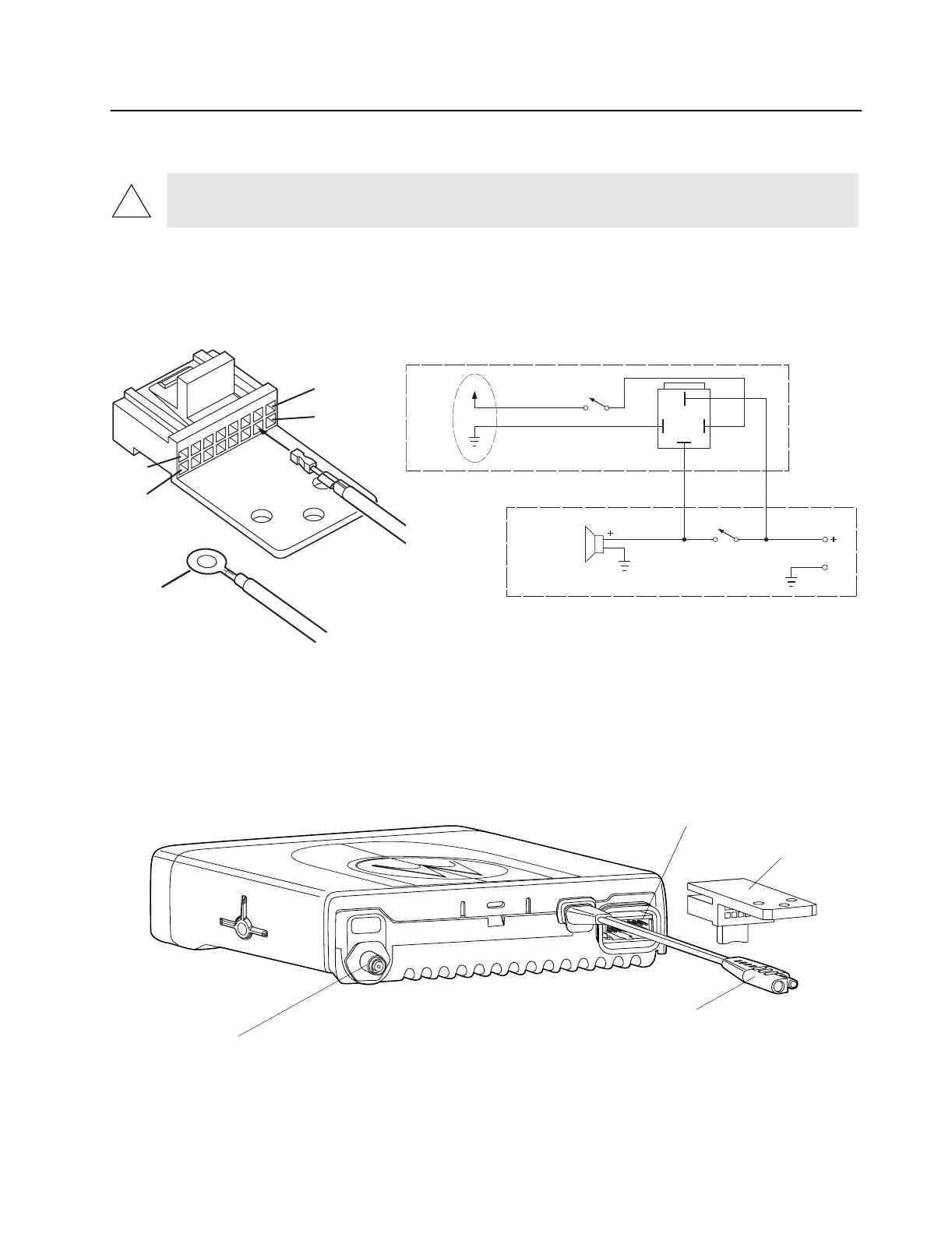
1. Plug the lead with the crimped-on terminal into the #4 socket of the accessory plug. (See Figure
6-1a).
2. Screw the circular terminal into the vehicle chassis.
3. Make all remaining wiring connections per wiring diagram. (See Figure 6-1b).
CAUTION: Do Not short pin 1, 13, or 16 on the accessory connector to Ground; this may damage the
radio.
Figure 6-2. Accessory Connector
To Vehicle
Chassis
(Blk)
MAEPF-22954-O
#1
#2
#16
#4
#15
J3-4
Red/Wht
Blk
External Alarm
On-Off Switch
Relay
(Bottom View)
Alarm Device
(Horn or Lights)
Horn Relay Contacts
or Light Switch
To Vehicle
Battery
Existing Vehicle Wiring
External Alarm Relay Kit
MAEPF-23082-A
Figure 6-1. HLN9328 External Alarm Configuration
a. accessory plug
b. wiring diagram.
Antenna
Connector
Connector
Housing
Accessory
Connector
Power
Connector
 Loading...