22 September 26, 2006 6809505A63-O
Disassembly V3xx
Removing and Replacing the Transceiver Board Assembly
1. Remove the battery cover, battery, USIM, antenna, rear housing and battery tray as
described in the procedures
.
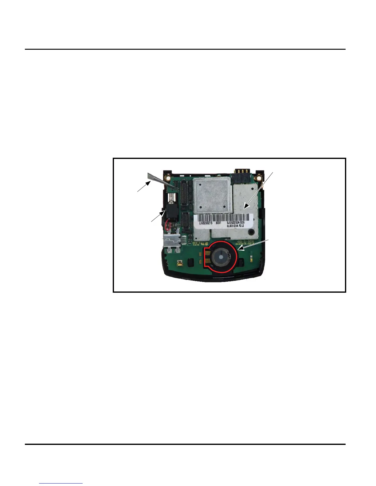
2. Use the plastic tweezers to pry loose and remove the vibrator assembly.
3. Lift the transceiver board assembly out of the front housing with the plastic tweezers. See
Figure 9.
4. To replace, insert the transceiver board assembly into the rear housing.
IMPORTANT During reassembly, make sure the PCB is not seated over the acoustic grommet.
5. Carefully and gently press the transceiver board into position and until it snaps into place.
6. Replace the antenna assembly, rear housing, USIM, battery, and battery cover as described
in the procedures.
G
This product contains static-sensitive devices. Use anti-static handling procedures
to prevent electrostatic discharge (ESD) and component damage.
061469o
Figure 9. Disconnecting the Flex from the Transceiver Board
Plastic
Tweezers
Transceiver PC Board
Assembly
Vibrator
Assembly
IMPORTANT!
During reassembly, make sure
the PCB is not seated over
the acoustic grommet.
 Loading...