HYDRIVE 2010A
Oil Flow Rate
15 - 32 US GPM 55 - 120 l / min
Circuit pressure
2 possible versions :
170 bar
270 bar
Maximum pressure allowed
RV set @ :
2465 PSI
5639 PSI
3983 PSI
RV set @ :
170 bar
270 bar
280 bar
Fan speed 2800 rpm 2800 rpm
Return pressure 15 - 75 PSI 1 - 5 bar
Heat Dissipation 13.5 HP for 70°F temperature rise 10 kw for 40 °C Temperature rise
Fan Motor Flow 1.5 U.S GPM 5.5 l / min
Weight (Dry) 53 lbs 24 kg
Oil Tank Capacity 2.5 US Gallons 10 liters
HYDRIVE 2020A
Oil Flow Rate 15 - 50 US GPM 55 - 190 l / min
Circuit pressure
Maximum pressure allowed
RV set @ 3675 PSI
4978 PSI
RV set @ 253 bar
350 bar
Fan speed 2800 rpm 2800 rpm
Return pressure 15 - 75 PSI 1 - 5 bar
Heat Dissipation 26 HP for 70°F temperature rise 20 kw for 40 °C Temperature rise
Fan Motor Flow 2.2 U.S GPM 8.2 l / min
Weight (Dry) 77 lbs 35 kg
Oil Tank Capacity 4.5 US Gallons 17 liters
4/16
NT 206-A00 10.11 Hydrive e
2. TECHNICAL DATA
3. INSTALLATION
3.1 Hydraulic circuits
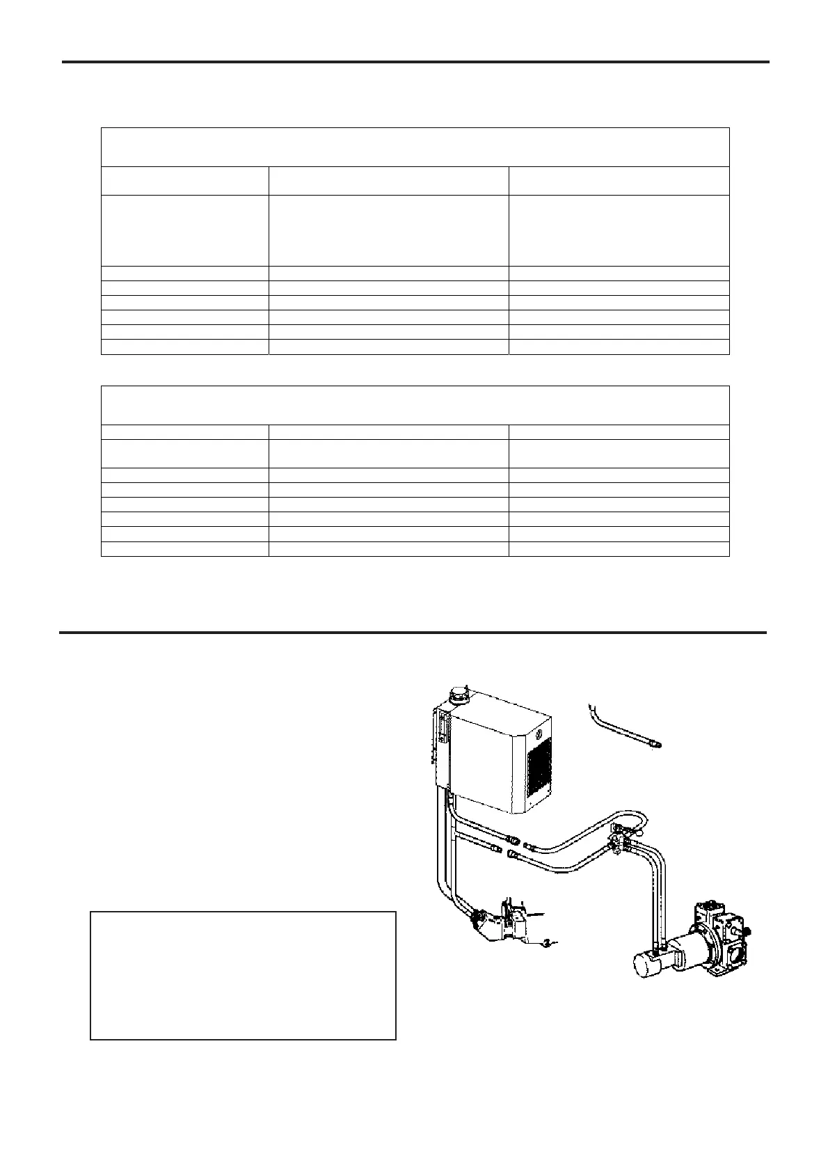
Figure 1 shows the hydraulic circuit for a single motor
drive system (without selector valve). If driving a motor
in both directions, install a directional control valve in the
circuit as shown (figure1).
The HYDRIVE is NOT suitable for use for systems using
tipping rams (hydraulic cylinders).
NOTE
Use bulkhead fittings to prevent any overstressing of the
hoses and connections between the tractor and trailer.
Figure 1
System layout without selector valve
HYDRIVE
PTO
Pump
Hydraulic
pump
Non-spill couplings
Directional
control valve
“T” connector
fitting
NOTICE :
The HYDRIVE must only be installed in sys-
tems designed by qualified engineering per-
sonnel. System design must conform with all
applicable regulations and codes and must
provide warning of all system hazards.