6/16
NT 206-A00 10.11 Hydrive e
3. INSTALLATION (continued)
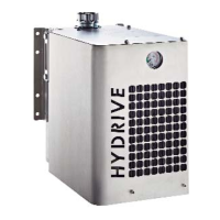
3.1.2 HYDRIVE 2010A HYDRAULIC CIRCUIT -
SELECTOR
1. Adjustable relief valve
2. Fan speed control valve
3. Return line filter
4. Fan motor
5. Filter by-pass valve
6. Oil cooler radiator
7. Fan
9. Return pressure gauge point
10. Selector
3.2 Mounting the HYDRIVE
1. Position the HYDRIVE so that the filler cap (5) and
sight glass (6) are accessible, and that the front of the
radiator (44) (where the air exits) is not obstructed.
NOTE - For easy installation, the sight glass can
be mounted on either side of the HYDRIVE tank.
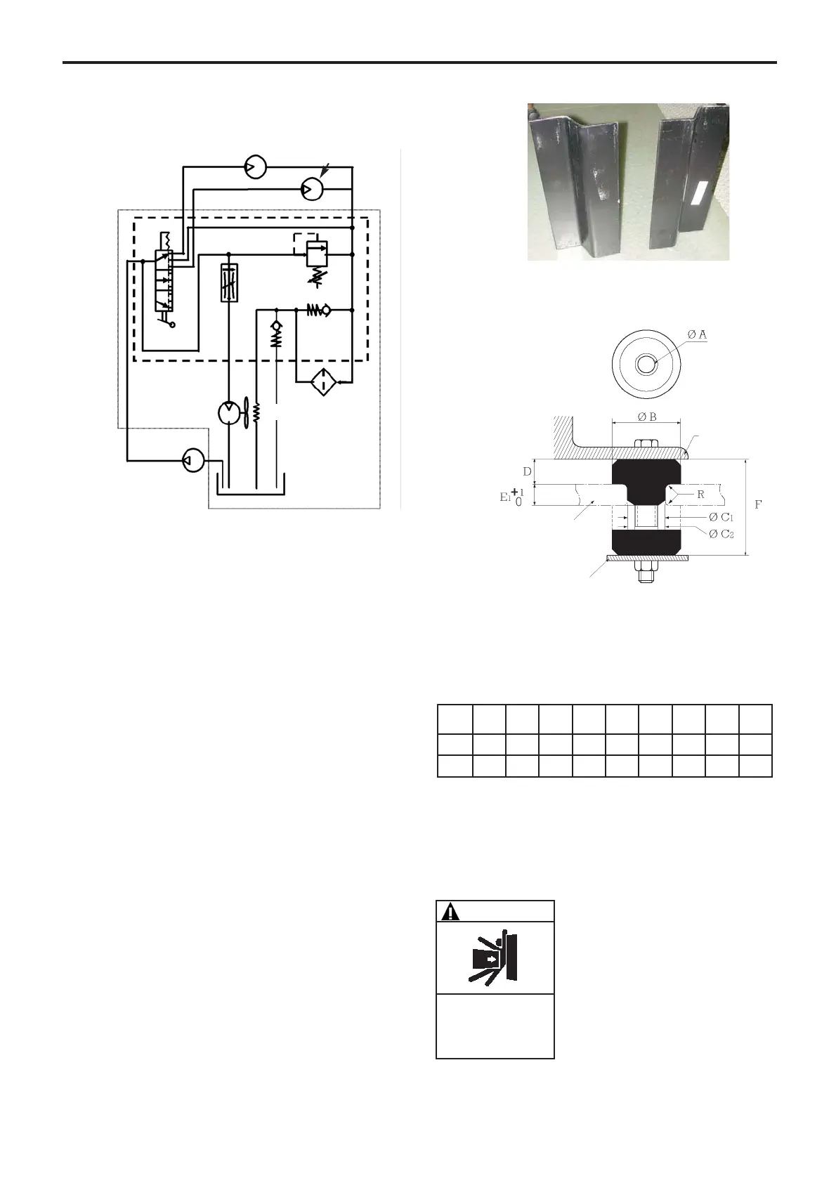
2. The HYDRIVE must be mounted using at least four of
the eight mounting holes and the anti-vibration pads
supplied (see Figures 3 and 4 below regarding moun-
ting dimensions). The minimum distance between
attachment points must be 7 inches (180 mm).
Do not put any strain on the tank fabrication (2) or dis-
tort the mounting lugs.
To help reduce the vibration and stress between the
truck frame and HYDRIVE, users may install additio-
nal mounting brackets to offset the HYDRIVE from the
frame rail and adapt the anti-vibration pads supplied.
The brackets are application specific and must be
made by the installer when needed.
The HYDRIVE must be mounted as high above the
hydraulic pump as possible to avoid hydraulic pump
cavitation.
C1 : Metallic bore Ø
C2 : Dampener Ø
F : Free height
R : Necessary radii on angles
Using the supplied washers contributes to the vibra-
tion protect.
3. Mount the HYDRIVE in a position away from the
wheels and road spray to protect the radiator from
impact damage from road debris, stones, loose hoses,
etc. (see Figure 3).
4. Allow provisions and space to install test equipment in
the discharge line of the HYDRIVE (see Figure 4).
WARNING
Hazardous machinery
can cause severe
personal injury
or property damage.
SET THE VEHICLE EMERGENCY BRAKE
AND CHOCK WHEELS BEFORE ATTEMP-
TING MAINTENANCE OR SERVICE.
Ø A
mm
Ø B
mm
Ø C1
mm
Ø C2
mm
D
mm
E1
mm
F
mm
R
mm
Weight
g
2010 10,4 33,2 19 20,1 12,3 9,5 31,7 1 43
2020 13,5 47,7 31,7 33 19,8 14 49,2 1,5 142
HYDRIVE
2010/2020
Washer (supplied)
Mounting braket
Hydraulic motor 2
Hydraulic motor 1
Oil tank
Hydraulic pump
Suction line
2
1
4
5
3
6
7
9
10
Oil HP