7/16
NT 206-A00 10.11 Hydrive e
3. INSTALLATION (continued)
3.2.1 CONNECTING THE HYDRIVE
1. Connect the suction hose from the HYDRIVE valve
block port marked "Pump" to the inlet of the hydraulic
pump via bulkhead fittings. The suction hose must be a
steel wire reinforced, vacuum rated, suction hose. See
chart below.
Do not put any strain on the tank fittings. The suction
hose must be as short as possible, without any tight
bends or kinks. The hose must also be free of air leaks.
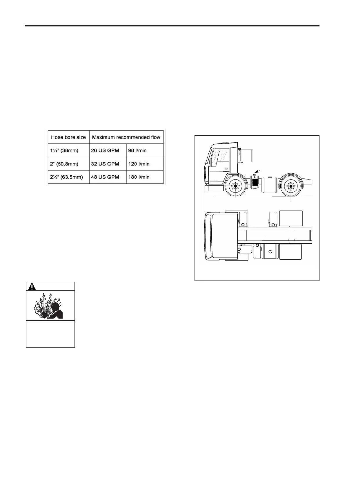
To minimize the possibility of cavitation, use the follo-
wing hose size guidelines :
NOTE
Hose length must follow hose manufactures
recommendations.
2. Pressure and return hoses must be connected using
pressure (swaged) type fittings, installed to the hose
manufactures recommendations.
3. All seals must be made using bonded washers, O-ring
or coned fittings.
MOUVEX does not recommend the use of PTFE tape
or liquid sealant, as these may contaminate the
hydraulic oil or plug the system.
4. Some hydraulic pumps and motors require a case
drain to return to the HYDRIVE tank. For these appli-
cations, remove the HYDRIVE tank drain plug (9) and
connect the drain line to ½" BSP female connection
(Figure 4, Item 4).
For HYDRIVE 2010's with selector valve option, go
to the step 1, Section 3.2.3.
3.2.2 HYDRIVE WITHOUT SELECTOR VALVE
1. Connect a high pressure hose from outlet of the hydrau-
lic pump to the inlet of the hydraulic motor. Insert a "T"
connector into this line and connect to the fitting on the
control block marked "MOTOR" (see Figure 1).
2. Connect the low pressure return hose from the driven
motor to the fitting on the control block marked
"RETURN". The return hose must be rated for mini-
mum 300 PSI (20 bar) working pressure (Figure 4,
Item 4).
For HYDRIVE 2010 without selector valve and
HYDRIVE 2020, go to the step 3, Section 3.2.3.
3.2.3 HYDRIVE WITH SELECTOR VALVE
1. Connect a high pressure hose from the male fitting on
the control block marked "MOTOR 1", to the intake of
the hydraulic motor (i.e. on the compressor). Connect
the fitting on the control block marked "MOTOR 2" to
the intake of the second hydraulic motor (i.e. on the
MOUVEX pump).
2. Using a "T" fitting, connect the low pressure return hoses
from both to the male fitting on the control block marked
RETURN". Use a return hose, rated to a minimum 300
PSI (20 bar) working pressure (Figure 5, Item 3).
NOTICE
For HYDRIVES fitted with the selector valve both
"MOTOR 1" & "MOTOR 2" MUST be connected to
HYDRIVE valve block fittings.
Optimum position
Various options for position
Figure 3
Mounting positions
Potential problem of cavitation
and road dirt
WARNING
Hazardous pressure
can cause
personal injury
or property damage.
SYSTEM FITTINGS AND HOSES MUST
BE CAPABLE OF WITHSTANDING
OPERATING PRESSURES.