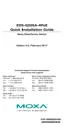
EasyManuals Logo

Moxa Technologies EtherDevice EDS-G205A-4PoE Hardware Installation Guide

Moxa Technologies EtherDevice EDS-G205A-4PoE
13 pages
To Next Page IconTo Next Page
To Previous Page IconTo Previous Page
Page #8 background imageLoading...
Page #8 background image
- 8 -
1000Base-T Pinouts
MDI Port
Pinouts
MDI-X Port
Pinouts
8-pin RJ45
Pin
Signal
Pin
Signal
1
BI_DA+
1
BI_DB+
2
BI_DA-
2
BI_DB-
3
BI_DB+
3
BI_DA+
4
BI_DC+
4
BI_DD+
5
BI_DC-
5
BI_DD-
6
BI_DB-
6
BI_DA-
7
BI_DD+
7
BI_DC+
8
BI_DD-
8
BI_DC-
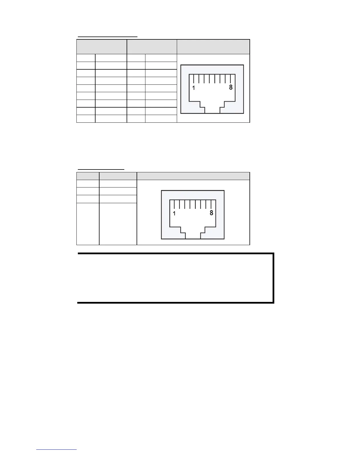
PoE Ethernet Port Connection
PoE ports located on the EDS switch’s front panel are used to connect to
PoE-enabled devices. The pinout follows the Alternative A, MDI mode” of
802.3af/802.3at standards. Please see the details in the following table.
PoE Port Pinout
Pin
Power
8-pin RJ45
1 V+
2 V+
3 V-
6 V-
NOTE
According to IEEE 802.3af/at standards, the PD shall be
implemented to be insensitive to the polarity of the power supply
and shall be able to operate per MDI mode and MDI
-X mode.
However, some PDs only support MDI mode or MDI
-X mode only.
The following figure shows how to select the correct cable
between the PD and EDS-G205A-4POE.

Other manuals for Moxa Technologies EtherDevice EDS-G205A-4PoE

Questions and Answers:

Question and Answer IconNeed help?

Do you have a question about the Moxa Technologies EtherDevice EDS-G205A-4PoE and is the answer not in the manual?

Moxa Technologies EtherDevice EDS-G205A-4PoE Specifications

General IconGeneral
BrandMoxa Technologies
ModelEtherDevice EDS-G205A-4PoE
CategorySwitch
LanguageEnglish

Related product manuals