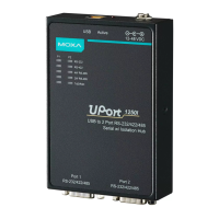
Connecting to a Serial Device
Use the proper serial cables to connect your serial devices to the UPort’s serial ports, which support the RS-232
and/or RS-422/485 interface. The UPort’s serial ports use DB9 male connector with standard pin assignment.
Please see Chapter 3 for detail pin assignment.
LED Indicators
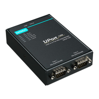
UPort 1250/1250I
There are five LEDs per port for indicating the status of the ports. The LEDs are listed under P1 and P2.
LED Name LED Color LED Function
Active
Red Power is on
Off Power is off, or power error condition exists
RS-232 Red Port is configured for RS-232 operation
RS-422 Red Port is configured for RS-422 operation
4W RS-485 Red Port is configured for 4-wire RS-485 operation
2W RS-485 Red Port is configured for 2-wire RS-485 operation
TxD/RxD
Orange Port is receiving data from attached device
Green Port is transmitting data to attached device
Off No data is being transmitted or received
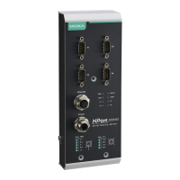
UPort 1400/1600
There are five LEDs per port for indicating the status of the ports. The LEDs are listed under P1, P2, P3, etc.
LED Name LED Color LED Function
Active Red Power is on; when the firmware is ready, the LED will turn green
If the device’s LED remains red, it means the firmware is not ready, and
the device cannot work properly
Green The device is ready
Flashing green The device is located by the Locate function on the host
Off Power is off, or power error condition exists
Tx/Rx Orange Port is receiving data from attached device
Green Port is transmitting data to attached device
Off No data is being transmitted or received
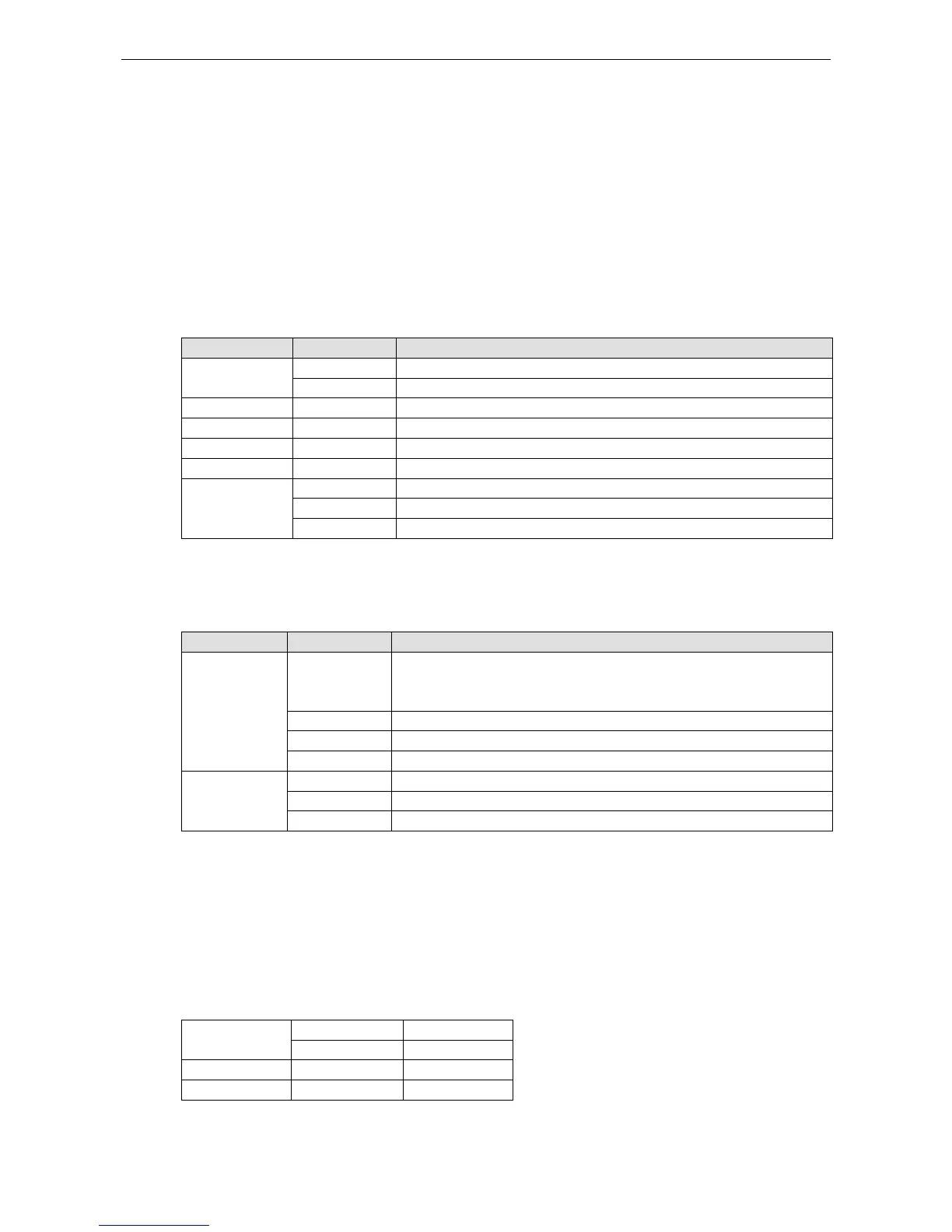
Adjustable Pull High/low Resistors for the RS-485 Port
The UPort uses DIP switches to set the pull high/low resistor values for each serial port.
To set the pull high/low resistors to 150 KΩ, make sure both of the assigned DIP switches are in the OFF
position.
To set the pull high/low resistors to 1 KΩ, make sure both of the assigned DIP switches are in the ON
position. This is the default setting.
SW
1 2
Pull High Pull Low
ON 1 KΩ 1 KΩ
OFF 150 KΩ 150 KΩ
 Loading...