4.3 Operang instrucons
When working with the load liing magnet, the pernent
industrial safety and accident prevenon regulaons are
to be observed.
In addion, liing magnet operaon may only be
started, if the operator knows the „Safety Regulaons
Magnet Operaon“ (see Table of Contents).
Before start-up of the power supply T 4002, the operator
should ensure that the 220V cable system is in an
opcally perfect condion. Plugs and plug connectors
are to be examined for ghtness of t, the anchoring
device of the magnet connecng cable is to be examined
for perfect funcon.
The V-belt tension with belt drives is to be examined and,
if necessary, the belts are to be reghtened according to
regulaon.
Unless otherwise expressly stated, the diesel engine
of the mobile excavator is to be brought up to full
revoluons. The generator then runs within its operang
range. The yellow LED „Ready“ automacally appears on
the mul-funcon display MFA I in the operator‘s cab.
Switching the power supply and/or the load liing
magnet on and o is usually accomplished with a
switch located in the handle. Depending on the type of
device, this must be energized with a separate switch
in the control console of the mobile excavator. For this
purpose also see the notes in the manual for the mobile
excavator.
If the switching-on command is given, then the generator
T 4002 connects the voltage contactless through to
the load liing magnet. If the command is given to
switch o, then the generator automacally leads to its
demagnezaon.
During the process of demagnezing, whereby the
magnet releases its load (approx. 1 sec), no renewed
switching-on command can be given.
Switching-on of the installaon is only possible, if a load
liing magnet is aached to the system.
Switching on the magnet:
Operate the buon in the control lever 1 x.
In addion to the yellow LED „Ready“, the green LED
„Power on“ lights up in the mul-funcon display.
Switching o the magnet:
Operate the same buon in the control lever again only
1 x.
The already illuminated green LED „Power on“ now goes
out and a red LED with „Power o“ lights up. Aer the
load has been dropped, this goes out automacally.
The permanently illuminated LED „Ready“ during the
shiing processes indicates that a renewed procedure is
now possible and that the power can be switched on.
Breakdowns are indicated by illuminated red LEDs.
The meaning and eliminaon of such disturbances are
explained using gurave illustraons and texts under
- Breakdown indicators on the MFA - (see 4.7 page
12/13).
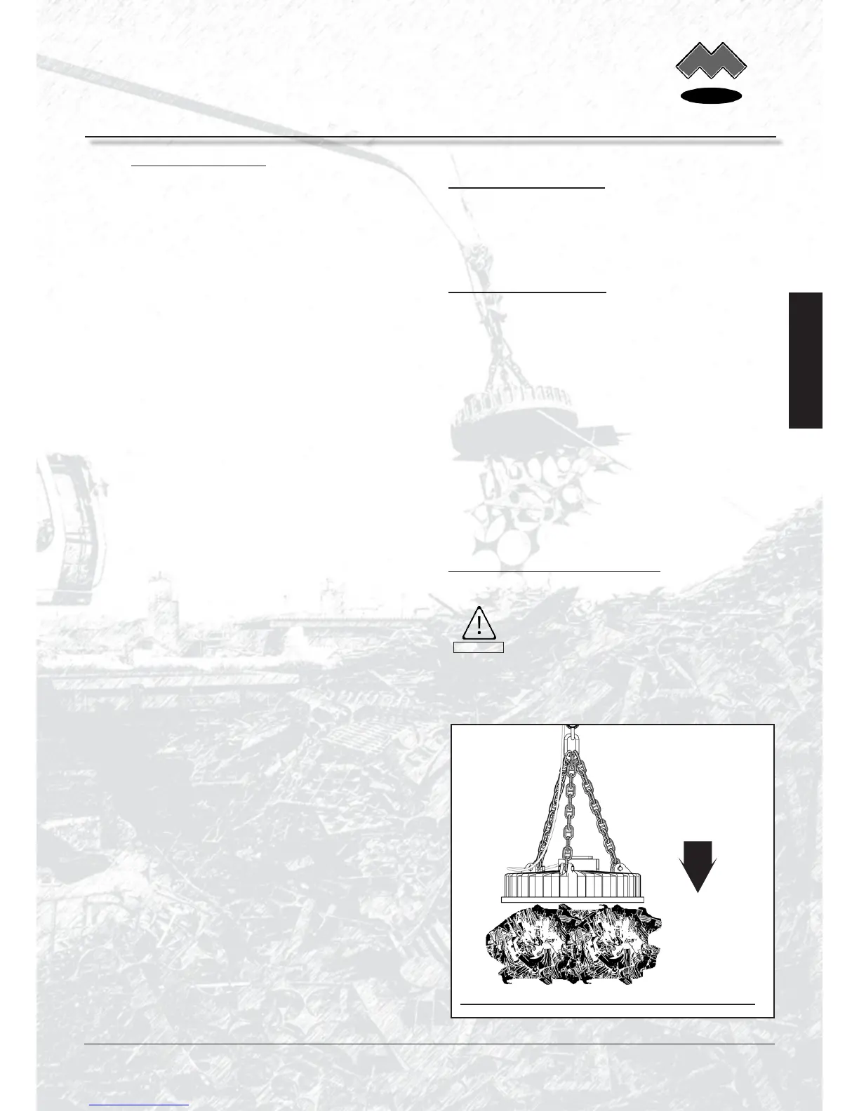
Operaon with load liing magnet:
First place the magnet on the
material and then switch it on.
Swivel the magnet back in a
switched-o state.
Fig. 9 | Touch down of the switched-o magnet on the material
First ‘touch down’
of the magnet, then
switch it on !
www.mozelt.com
CAUTION
Englisch
MOZELT GmbH & Co. KG
Load liing magnet devices
Technical Manual: Electrical Power Supply T4002
Copyright: MOZELT GmbH & Co. KG, D-47269 Duisburg Edition: May 2012 -9-