SCADA REGISTERS
Register
Address
Read
Write
Description of Register Contents
(Where a Coil is represented by a Bit in a Register)
40001 √
40002 √ √
40003 √ Pump 1 Elapsed Time Meter (hours and 1/10 hours) Range: 0.0
-
6553.5 hours
40004 √ Pump 2 Elapsed Time Meter (hours and 1/10 hours) Range: 0.0
-
6553.5 hours
40005 √ Pump 3 Elapsed Time Meter (hours and 1/10 hours) Range: 0.0
-
6553.5 hours
40006 √ Pump 4 Elapsed Time Meter (hours and 1/10 hours) Range: 0.0
-
6553.5 hours
40008 √
40009 √ √
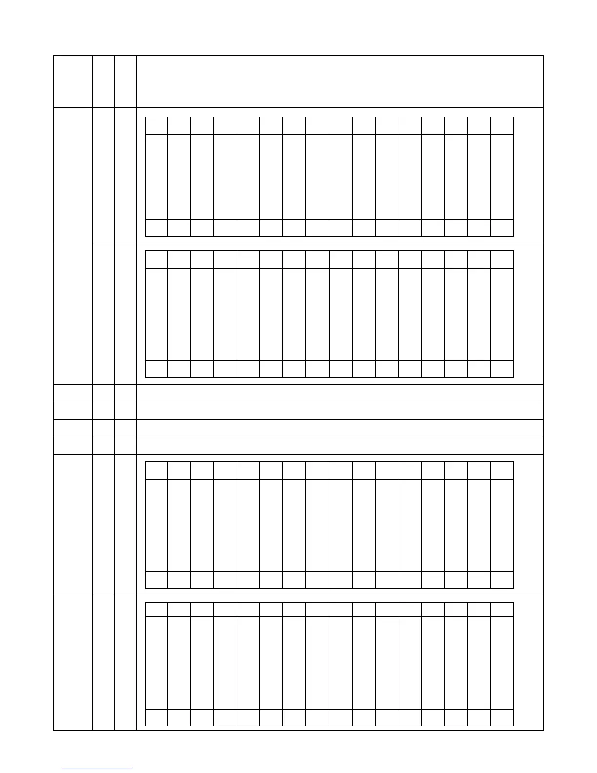
16 15 14 13 12 11 10 9 8 7 6 5 4 3 2 1
Pump Called On
Level Probe Backup
Telemetry D
Discrete Input Function 30
On Generator
Discrete Input Function 7
All Pump Disable
Discrete Input Function 8
Telemetry C
Discrete Input Function 29
Telemetry B
Discrete Input Function 28
Pump Called On
Float Backup
Telemetry A
Discrete Input Function 27
Disabled Pump Operation
Discrete Input Function 31
Telemetry M
Discrete Input Function 26
Telemetry L
Discrete Input Function 25
Telemetry K
Discrete Input Function 24
Telemetry J
Discrete Input Function 23
Low Level Alarm
From All Sources
High Level Alarm
From All Sources
15 14 13 12 11 10 9 8 7 6 5 4 3 2 1 0
Coil
Bit
28
32 31 30 29 28 27 26 25 24 23 22 21 20 19 18 17
FLC & LFC
-
Reset
P4 Relay Remote Control
With Parameter F.36 = 2
P3 Relay Remote Control
With Parameter F.35 = 2
P2 Relay Remote Control
With Parameter F.34 = 2
P1 Relay Remote Control
With Parameter F.33 = 2
LO Relay Remote Control
With Parameter F.32 = 2
HI Relay Remote Control
With Parameter F.31 = 2
ETM 4
-
Reset
ETM 3
-
Reset
ETM 2
-
Reset
ETM 1
-
Reset
Pump 4
Remote Control
Force Pump On
Pump 3
Remote Control
Force Pump On
Pump 2
Remote Control
Force Pump On
Pump 1
Remote Control
Force Pump On
15 14 13 12 11 10 9 8 7 6 5 4 3 2 1 0
Coil
Bit
128 127 126 125 124 123 122 121 120 119 118 117 116 115 114 113
Low Level Float Level
Discrete Input Functions 17, 32
1st Pump On Level Float
Discrete Input Function 34
2nd Pump On Level Float
Discrete Input Function 35
3rd Pump On Level Float
Discrete Input Function 36
4th Pump On Level Float
Discrete Input Function 37
High Level
(Level Probe Backup)
Low Level
(Level Probe Backup)
High Level Float
Discrete Input Functions 18, 38
Off Level Float
Discrete Input Function 33
On Generator
Discrete Input Function 7
All Pump Disable
Discrete Input Function 8
Telemetry H
Discrete Input Function 22
Telemetry G
Discrete Input Function 21
Telemetry F
Discrete Input Function 20
Telemetry E
Discrete Input Function 19
15 14 13 12 11 10 9 8 7 6 5 4 3 2 1 0
Coil
Bit
144 143 142 141 140 139 138 137 136 135 134 133 132 131 130 129
Flush Cycle Active
Stop Flush Cycle
Start Flush Cycle
Force Alternation
Low Level (When Level is
At or Below Alarm Setting)
High Level (When Level is
At or Above Alarm Setting)
15 14 13 12 11 10 9 8 7 6 5 4 3 2 1 0
Bit
Coil
 Loading...