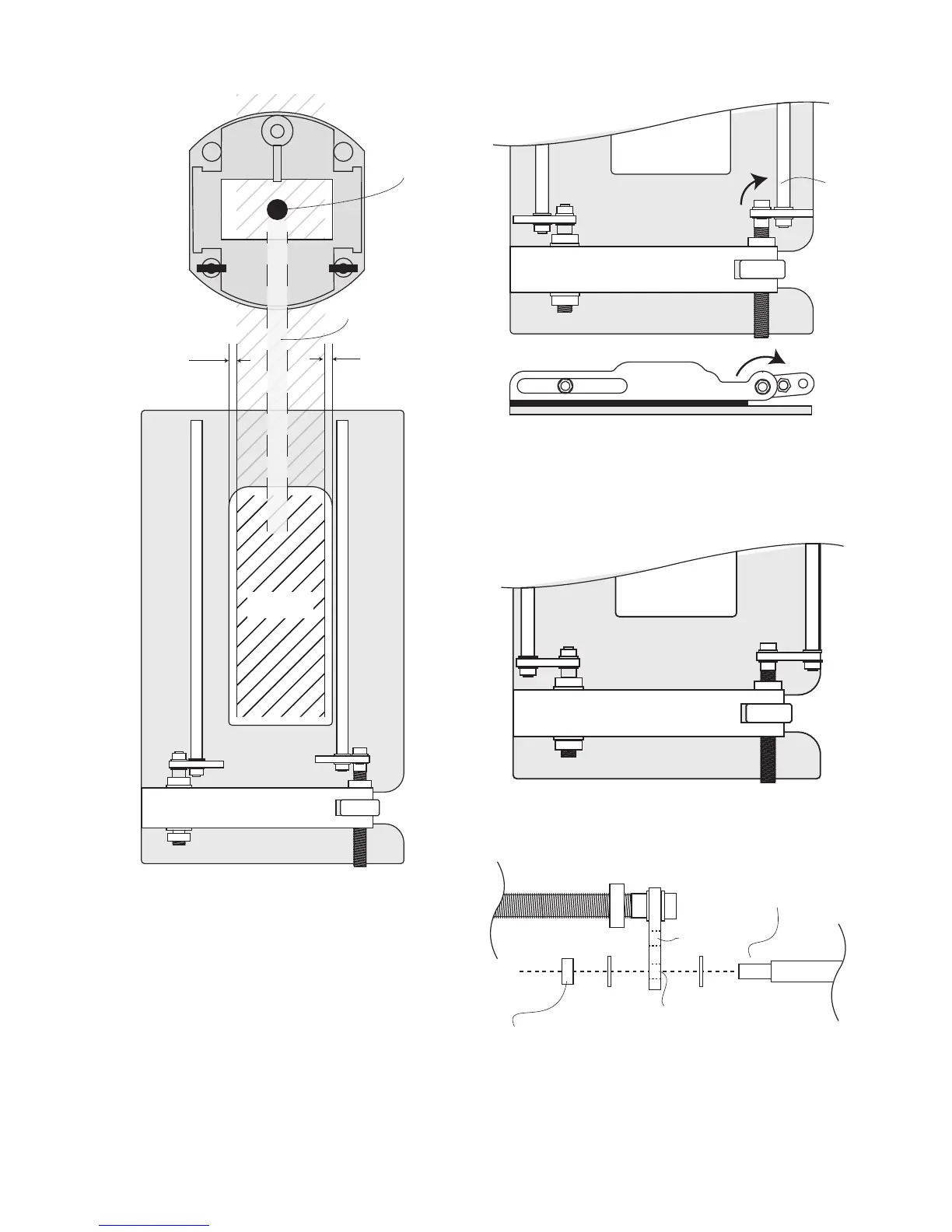
5. Guide Rod adjustment4. Cutter alignment
Router
cutter
Letterbox
Router cutter
path
* 1/4”
Clearance
*
X
X
5
5E2
6E2
5B
5
5E1
5E2
Check that the router cutter will safely align
within the letterbox cross hatch area.
IF IT WILL, GO TO STEP 7.
IF IT WILL NOT, GO TO STEP 5.
Loosen the M5 nut (5B) using a 5/16” spanner.
Move the adjuster rod (5) to the other crank
plate drilling (5E2).
Replace washers and nuts and tighten.
For further adjustment fit the rods in the other
crank plate drillings (5E2 & 6E2).
Flip cranked adjuster rod (5) to its outer
position.
6. Crank Plate adjustment
5