Tip: Positioning the router base Wing Bolts
towards the bridge end of the CRB7 will increase
micro adjuster accuracy.
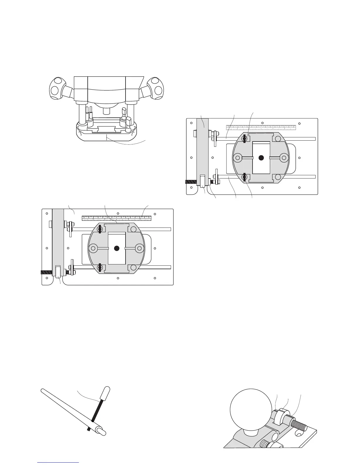
Using the index markings
The micro adjuster and bridge have
corresponding red index lines. (1A & 4A)
1 x Micro adjuster rotation = 5/100” (1.25mm).
4 x Rotations = 3/16” (5mm).
Removing the slack from the adjuster
thread.
• Loosen both router base wing bolts and turn
the adjuster (4) in the desired direction to
engage the thread.
• Rotate until index markings (1A & 4A) align.
• Re-tighten the wing bolt on the adjuster guide
rod.
• Should the router cutter need to be adjusted
in the opposite direction repeat the above
step.
Once happy with the rule location:
• Ensure that the baseplate (2) is clean.
• Peel off the self adhesive backing paper.
• Stick in position.
THE LOCK BARS
Use the lock bars (18) to help tighten and
loosed the guide rods.
THE SELF ADHESIVE RULE
11A
16 4 3 27 1 2 3 4 5 6 7
123 1 2 3
cm
Inches
5
11
11A2
4
THE MICRO ADJUSTER
• Plunge the router cutter to a level just above
the workpiece and lock in position.
• Loosen the router base wing bolt (I6) on the
fixed guide rod (6).
• Lock the router base wing bolt (I5) on the
adjuster guide rod (5).
• Rotate the micro adjuster (4) to move the
router and cutter into position.
• Lock the adjustment in position by tightening
the adjuster nut (4B) against the bridge (1).
4B
Many routers are manufactured with a cast
index line (11A).
• If the router has no index line, draw one
on the base using a fine tip marker pen.
7
18
With the router fitted to the CRB7:
• Position the rule (11) along the edge of the
router base.
A measurement can then be taken as the router
is moved.
16 4 3 27 1 2 3 4 5 6 7
123 1 2 3
cm
Inches
5
61 I6
I5
4
1A
1A
5
4A