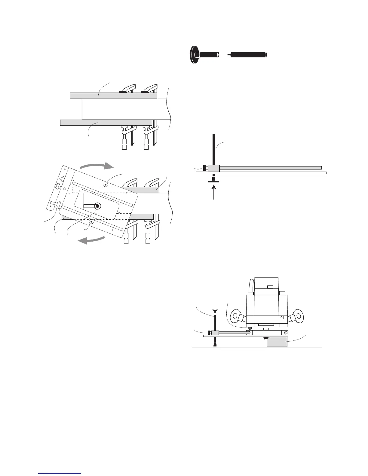
• Slide the anti-tilt leg (8) into the bridge
from the underside.
• Tighten the bridge pinch bolt (3) to lock it in
position.
• Slide the router onto the CRB7 rods and lock
in position using the wing bolts (I)
• Rest the CRB7 and router on the work piece
(M), then release the bridge pinchbolt (3) to
set the anti-tilt Leg depth.
• Lock the anti-tilt Leg in position.
Before routing, check that the bench
surrounding the work piece is smooth, even
and clear of obstacles.
Anti-Tilt Support
The Anti tilt leg is a two part assembly.
Max. Support height = 3 1/8” (80mm)
Min. support height = 5/16” (8mm)
If the mortise is positioned at the end of
the work piece, clamp extended battens (L)
to either side.
L
Workpiece
L
L
L
K
10
10
Workpiece
4
Check that the mortise pillars can complete
the mortise without running off the end of
the battens.
For a deep mortise, several light cutting
passes may be preferred.
9
8
3
8
3
M
I
When cutting the mortise, ensure an even
pressure is maintained between the
mortise pillars and workpiece.