5 Installation and commissioning
57BA5831400-00 EN
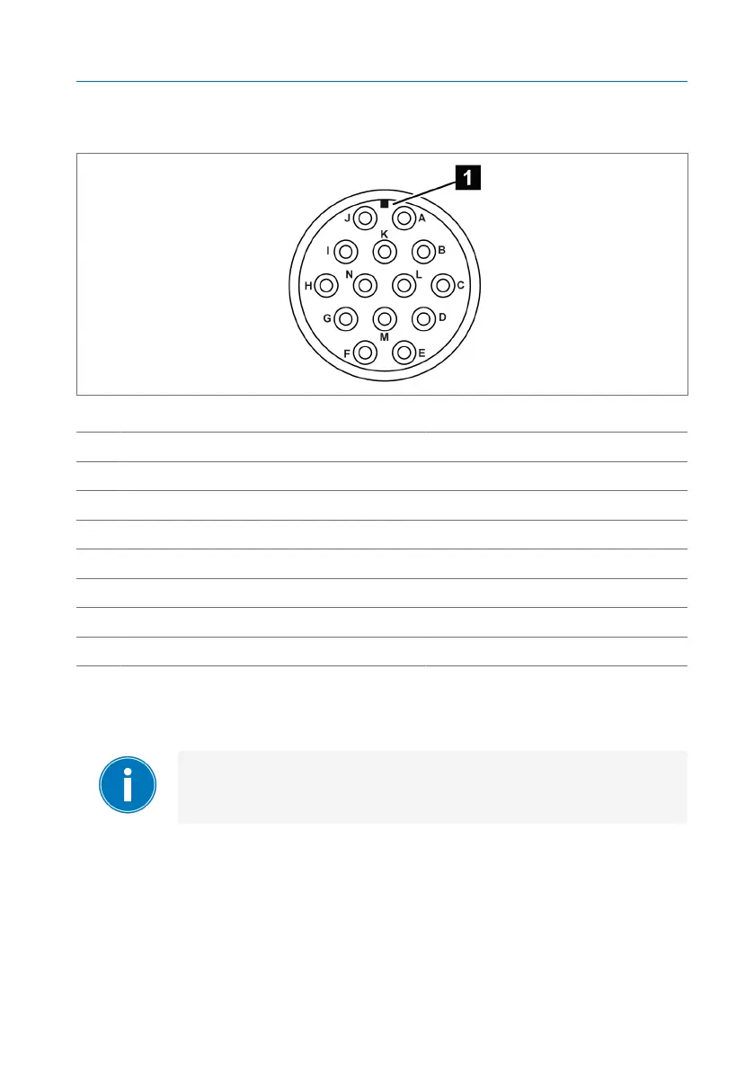
3. Connect the wires at the free end of the connection cable in the control
cabinet in accordance with the supplied connection diagram.
Figure41: Connection assignment, view of installed M plug
1 Coding contour
A Black B Red
C Blue D Orange
E Yellow F Brown
G Red/black H Blue/black
I Orange/black J Yellow/black
K Brown/black L Black/red
M - N -
5.4.6.3 Connecting the micro-switches using the ANSI plug (Compact
RM)
Devices with a plug connection may be set up with either only
extra-low-voltage circuits or only low-voltage circuits using the
device plug.
 Loading...