Page 11
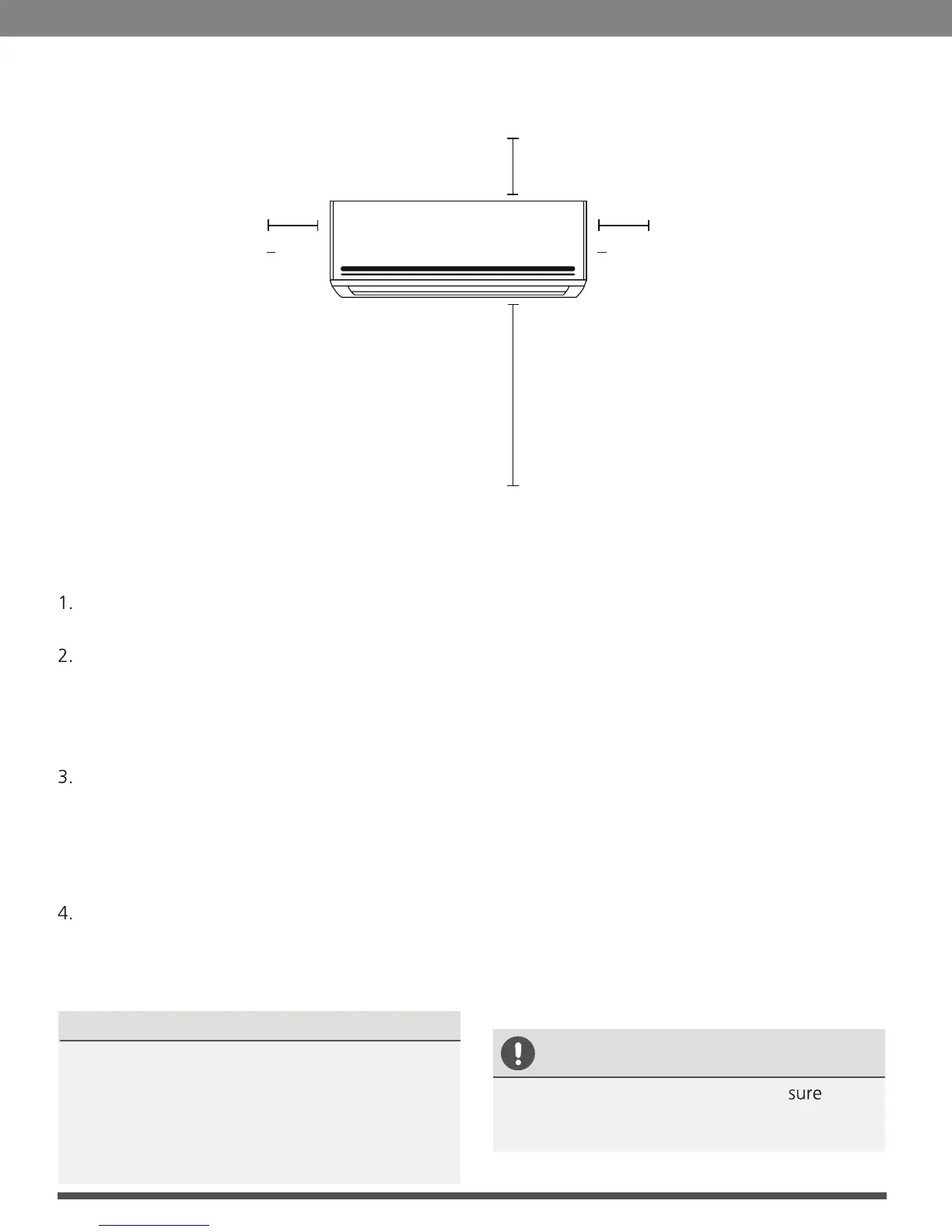
Refer to the following diagram to ensure proper distance from walls and ceiling:
Step 2: Attach mounting plate to wall
The mounting plate is the device on which you
will mount the indoor unit.
Remove the screw that attaches the mounting
plate to the back of the indoor unit.
Place the mounting plate against the wall in a
location that meets the standards in the
Select Installation Location step. (See
Mounting Plate Dimensions for detailed
information on mounting plate sizes.)
Drill holes for mounting screws in places that:
• have studs and can support the weight of
the unit
• correspond to screw holes in the mounting
plate
Secure the mounting plate to the wall with
the screws provided.
5. Make sure that mounting plate is flat against
the wall.
r
the wall.
NOTE FOR CONCRETE OR BRICK WALLS:
If the wall is made of brick, concrete, or similar
material, drill 0.2in-diameter (5mm-diameter)
holes in the wall and insert the sleeve anchors
provided. Secure the mounting plate to the
wall by tightening the screws directly into the
clip anchors.
Step 3: Drill wall hole for connective piping
You must drill a hole in the wall for refrigerant
piping, the drainage pipe, and the signal cable
that will connect the indoor and outdoor units.
1. Determine the location of the wall hole based
on the position of the mounting plate. Refer
to Mounting Plate Dimensions on the
next page to help you determine the optimal
position. The wall hole should have a 2.5in
(65mm) diameter at least, and at a slightly
lower angle to facilitate drainage.
2. Using a 2.5in (65-mm) core drill, drill a hole in
the wall. Make sure that the hole is drilled at
a slight downward angle, so that the outdoor
end of the hole is lower than the indoor end
by about 0.2 to 0.275in (5mm-7mm). This will
ensure proper water drainage. (See
Fig. 3.2
)
3. Place the protective wall cuff in the hole. This
protects the edges of the hole and will help
seal it when you finish the installation process.
CAUTION
When drilling the wall hole, make to
avoid wires, plumbing, and other sensitive
components.
Fig. 3.1
Indoor Unit Installation
Minimum Ceiling
Clearance is
15cm (5.9in)
(4.75in)
>12cm
(4.75in)
>12cm
For Ceilings Greater
Than 9 Foot Suggested
Floor Clearance is
230cm(90.55in)
For Ceilings Less
Than 9 Foot Suggested
Floor Clearance is
200cm(78.55in)
 Loading...