Figure 11
Figure 12
INSTALLATION (continued)
INTERFACE CARD INSTALLATION:
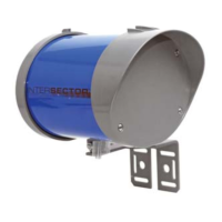
Route the other end of the Ethernet cable to your cabinet. Connect the Ethernet
connector to the end of the cable. Configure the Ethernet connector (RJ45 plug) for a
“Straight thru” connection.
NOTE: Your colors may be different than what is shown.
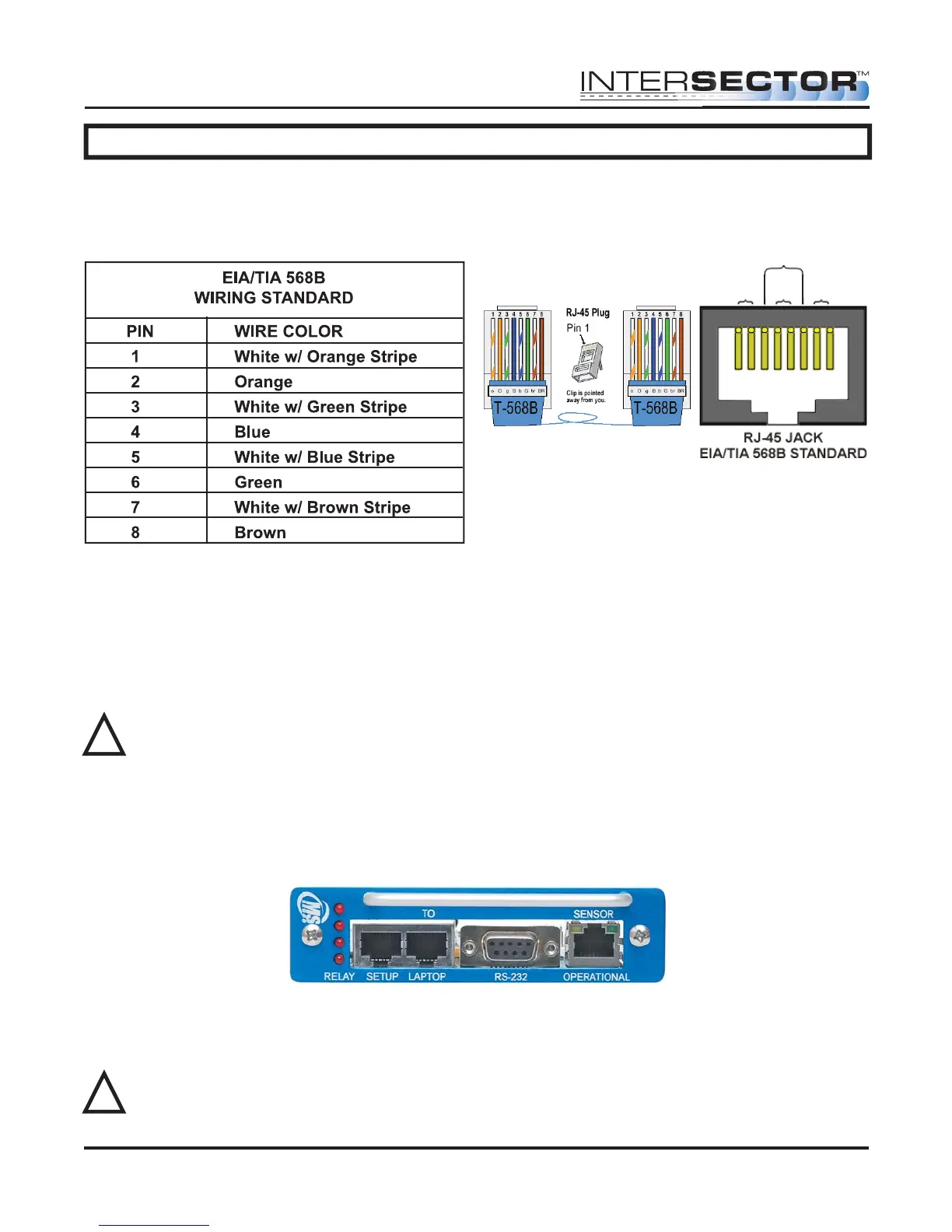
After completing the Ethernet cable, plug the interface card into your traffic cabinet.
• If using the 4 output interface card, ensure that it is plugged into the even slot.
• If using the 2 output interface card, it can be plugged into any slot.
Either card uses 12-24 Volts supplied by the rack in the cabinet.
CAUTION: Power supply must be capable of supplying 1 amp of current to each
TCIB card.
Once the interface card is properly installed, plug the Ethernet cable from the sensor
into the setup port of the card. Initially the LEDS will light and stay on when the Ethernet
cable is plugged into the setup port. This is normal and indicates that the unit has not
been completely setup. Once a valid connection is established the LED will light only
when the zone is activated by vehicle detection. The sensor is now ready to program.
SOFTWARE SETUP:
Programming of the INTERSECTOR is performed by connecting the sensor to a
computer. Connect a Laptop/PC to the Laptop Ethernet port.
WARNING: The INTERSECTOR can only be programmed if the Ethernet cable is
plugged into the setup port on the interface card. Please ensure proper
connection before proceeding further.
INTERSECTOR
Microwave Motion and
Presence Sensor Installation Instructions
MS Sedco INTERSECTOR Installation Instructions Page 12 INTERSECTOR-1.9Uv092717
!
!
Brown
Pair 4
Orange
Pair 2
Blue
Pair 1
Green
Pair 3