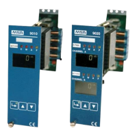
Control Unit Models 9010 LCD and 9020 LCD
14
Configuration
MSA
GB
5 Configuration
5.1 Control Unit Configurations
The board was designed and certified to satisfy Directive 94/9CE, better known as
ATEX Directive, in order to be suitable for monitoring gas and/or flammable vapours in the field
of the Lower Limit of Explosiveness [LIE] and in order to detect the deficiency or enrichment of
oxygen.
The directive imposes some functional links of the Control Unit with the aim of guaranteeing the
safety of the monitored area and therefore of the persons that operate it.
When jumper CV23 is done, the board operates in ATEX mode [default configuration].
In this case, the functioning of the Control Unit turns out to be very rigid and some modes of op-
eration, available when the board is used for other aims, cannot be set.
IMPORTANT
With the functioning mode according to the ATEX Directive, particular importance is attributed to
the FAILURE function that, via the relative opto-isolator or relay, signals any out-of-service condi-
tion of the Control Unit, even if not attributable to a failure.
This prerogative, resulting from an exasperated operating condition as a function of safety, must
be kept in the debit account by the Designers of the installations monitored via the Control Unit if,
resulting from the FAILURE condition, is made to correspond to an important action in the opera-
tion of the installations themselves.
Among the situations that provoke the FAILURE condition, the following should be remembered:
- Entry in any of the Access Codes.
- Blocking of the alarms
5.2 Front Panel
Located on the front panel are:
- 4-digit back-lit LCD display [no. 2 in the case of model 9020]. On the display, beyond the value
of the concentration, different information is available, such as the engineering unit, delay
alarms, their possible blocking, the calibration and TIME OUT states, as well as the symbols
of reference to possible conditions of operational irregularity.
- 3 LED [C; W, A] for the optical indication of reaching the alarm levels.
- LED [F] for the optical indication of a possible failure or out-of-service condition.
- Pockets suitable for containing the identification of the type of gas that is monitored.
- 3 buttons, as represented below, to enable all of the operations necessary for managing the
Control Unit.
Enter key used in order to select the access codes and confirm the settings
of the data.
A green LED is inserted in the button that signals by continuous light that the
device is turned on and by flashing light the entry of an access code.
UP key for increasing the data to be modified in the access codes or for si-
lencing and resetting the alarms
Down key for decreasing the data to be modified in the access codes or for
silencing and resetting the alarms

 Loading...