EasyManua.ls Logo

MSA General Monitors S4100C User Manual

MSA General Monitors S4100C
42 pages
To Next Page IconTo Next Page
Page #1 background imageLoading...
Page #1 background image
MODEL S4100C
Hydrocarbon Smart Transmitter
Hydrocarbon Sulphide
Smart Transmitter
Hydrocarbon Sulphide
Smart Transmitter
Hydrocarbon Sulphide
Smart Transmitter
Hydrocarbon Sulphide
Smart Transmitter
Hydrocarbon Sulphide
Smart Transmitter
Hydrocarbon Sulphide
Smart Transmitter
Hydrocarbon Sulphide
Smart Transmitter
Hydrocarbon Sulphide
Smart Transmitter
Hydrocarbon Sulphide
Smart Transmitter
Hydrocarbon Sulphide
Smart Transmitter
The information and technical data disclosed in this
document may be used and disseminated only for
the purposes and to the extent specifically
authorized in General Monitors in writing. Such
information and technical data are proprietary to
General Monitors and may not be used or
disseminated except as provided in the foregoing
sentence.
Instruction Manual 01/18
General Monitors reserves the right to change published
specifications and designs without prior notice.
Part No. MANS4100C-EU
Revision Q/01-18
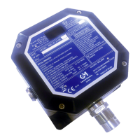
Table of Contents

Question and Answer IconNeed help?

Do you have a question about the MSA General Monitors S4100C and is the answer not in the manual?

MSA General Monitors S4100C Specifications

General IconGeneral
Product TypeTransmitter
ModelS4100C
ManufacturerMSA General Monitors
Output Signal4-20 mA
Detection PrincipleElectrochemical
Power Supply24 VDC
Hazardous Area CertificationATEX, IECEx
Enclosure RatingIP66
Operating Temperature-40°C to +75°C
Relative Humidity0-95% RH (non-condensing)
EnclosureStainless steel

Summary

Declaration of Conformity

EMC Directive Compliance

Conformity with EMC Directive 2014/30/EU, listing report numbers and standards.

ATEX Certification

Compliance with ATEX Directive 2014/34/EU, listing certificate number and protection.

Warranty Statement

Warnings

Introduction

General Description

Detailed description of the Model S4100C, its features, and user interface.

Specifications

Approvals

Lists Hazardous Area Standards and Codes of Protection applicable to the transmitter.

Functional

Details the operational parameters such as measuring range, trip levels, and output types.

Mechanical

Provides physical dimensions, weight, and mounting details for the transmitter.

Environmental

Specifies operating temperature, humidity, altitude, and EMI/RFI susceptibility.

Electrical

Outlines supply voltage, current, fuse ratings, and analogue output characteristics.

Factory default settings

Lists the default configuration values for calibration, trip levels, and Modbus settings.

Sensor Material and Specifications

Describes sensor construction materials and classifications when connected to the S4100C.

Outline Drawing

Illustrates the physical dimensions and connections of the Model S4100C transmitter.

Installation

On Receipt of your Equipment

Instructions for checking the equipment upon delivery and reporting discrepancies.

Smart Transmitter location Guidelines

Recommendations for selecting the optimal location for installing the Smart Transmitter.

Sensor Poisons

Information on substances that can adversely affect the performance of HC sensors.

Interconnecting cable Guidelines

Requirements and recommendations for selecting and routing interconnecting cables.

Installation of Sensor

Procedure for physically mounting the sensor into the junction box with proper sealing.

Smart Transmitter Cable Termination

Detailed steps for terminating cables at the transmitter, including grounding and screen connections.

Cable Termination in Safe Area

Guidelines for proper cable armour and screen termination in safe area enclosures.

Cable Termination Drawing

Diagrams illustrating cable termination for integral and remote sensors and safe area connections.

Interconnection Details

Table specifying signal names, terminal assignments, and module fly lead colours.

Power up Routine

Describes the sequence of operations and display indications during instrument power-up.

Stopping Plug Installation

Instructions for correctly installing or re-installing the stopping plug in the transmitter housing.

Maintenance

Maintenance

Describes routine checks, sensor accessory care, and system testing recommendations.

Storage

Guidelines for storing the modules in a clean, dry area and protecting them during prolonged storage.

Trouble Shooting

Fault codes and Remedies

Table listing fault codes, their priority, mode, and recommended remedies for troubleshooting.

Alarms

Explanation of how alarms are displayed, prioritized, and cleared.

Modbus RTU Serial Interface problems

Procedures for resetting Modbus parameters to factory defaults when issues arise.

Ancillary Equipment

Dust Guard Assembly

Description and purpose of the dust guard accessory for sensor protection.

Sintered Stainless Steel Dust Guard

Details of a dust guard providing fine particulate protection, suitable for dry environments.

Splash Guard

Description of a guard designed to deflect water spray and protect the sensor from rain and wind.

Sensor Flow Chamber

Information on a chamber for inserting sensors into sampling systems.

Duct Mounting Plate

Description of a mounting plate for installing sensors in ducted air systems.

Portable Purge Calibrator

Overview of a field calibration system using gas/air mixtures.

Portable Purge Calibrator Operating Instructions

Step-by-step guide for calibrating the transmitter using the portable calibrator.

Remote Test Gas Applicator

Details of an applicator for applying test gas to sensors from a remote source.

Volatile Liquids and Solvents

List of volatile liquids and their required volumes for 50% LEL calibration.

Modbus RTU Serial Interface

General

Overview of the Modbus RTU interface, addressing, and network configuration.

Modbus Message Characteristics

Details on baud rate, byte length, and message spacing for Modbus communication.

Modbus Exception Codes

List of standard Modbus exception codes and their descriptions.

Modbus Read/Write - Commands

Description of Modbus function codes for reading and writing data to the transmitter.

Modbus Register Configuration

Details the Modbus registers used for configuration and data access.

Register 3

Explains the bit assignments for alarm, fault, and analogue output status.

Register 7

Details bit assignments for open collector outputs and analogue output at calibration.

Register 9

Describes bit assignments for Modbus node address, stop bits, parity, and baud rate.

Register 10

Explains the use of Register 10 for clearing latched faults and alarms.

Appendix A

Maximum Sensor Cable Length

Table showing maximum sensor cable lengths for various conductor sizes.

Maximum Smart Transmitter Cable Length

Table showing maximum transmitter cable lengths for different conductor sizes and voltages.

Customer Satisfaction Questionnaire

Related product manuals