Model S4100C
18
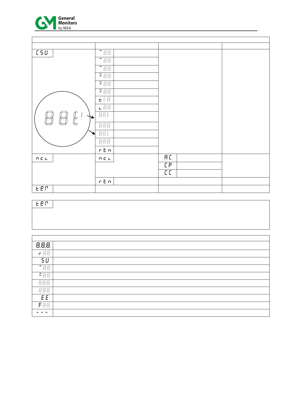
TABLE 1 – MENU DISPLAY CODES
A1 open collector output
norm. (de)-energized
A1 open collector output
(non)-latching
A2 open collector output
norm. (de)-energized
A2 open collector output
(non)-latching
Analogue output current
during calibration in mA
Response @ cal in % of
mV reference
Nr. Of successful
calibrations
Modbus port 1 & 2 node
address
Activate calibration,
Apply calibration gas
Note: This operation sets
nr. of calibrations to
1 and redefines
sensor mV reference
when successful
Calibration completed,
Remove calibration gas
“10 sec Menu Timeout in progress”. This timeout starts 30 sec after the last menu selection was made.
Apply magnet to re-enter at Level 1. The analogue output remains at calibration level in this mode.
If magnet not applied, the instrument will write menu parameters to EEPROM,
exit menu and revert to normal operation following timeout.
Software Revision (1 sec)
Power up in progress (58 sec)
Gas measurement with A1 alarm condition present, or latched A1 alarm pending
Gas measurement with A2 alarm condition present, or latched A2 alarm pending
Slow Flash (2/sec) “Overrange” if display > 99% LEL or “Check Calibration Mode active”
Rapid Flash (8/sec) “Acknowledgement of menu selection” or “Magnet present” during alarm or fault indication


 To Next Page