Do you have a question about the MSI H67MS-E23 B3 series and is the answer not in the manual?
Intellectual property and usage terms for the document.
List of registered trademarks and their owners.
Details of manual revisions and release dates.
Information on obtaining assistance and resources.
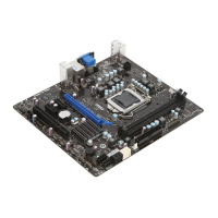
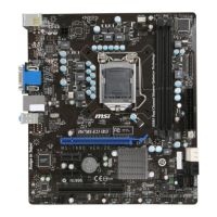
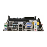
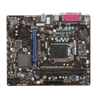
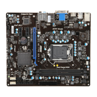
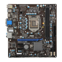
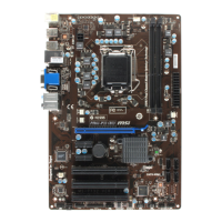
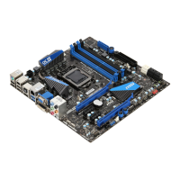
Identification of external ports and internal headers.
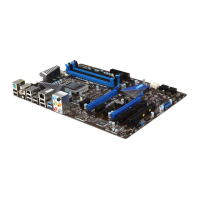
Details on available PCIE and PCI slots for add-on cards.
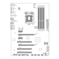
Physical dimensions and installation hole layout.
Description of the 24-pin and 4-pin ATX power connectors.
Specification for CPU and system fan power headers.
Pinouts for front panel switches, LEDs, and audio.
Details on connecting front panel USB devices.
Pinout for the front panel audio header.
Description of the digital audio output connector.
Pinout for the RS-232 serial communication port.
Pinout for the parallel printer port.
Function of the chassis intrusion detection switch.
Procedure for resetting BIOS settings via jumper.
Details on Peripheral Component Interconnect Express slots.
Details on Peripheral Component Interconnect slots.
Explanation of keyboard commands used in BIOS setup.
Guide to navigating BIOS menus and accessing help.
| Form Factor | Micro ATX |
|---|---|
| Socket | LGA 1155 |
| Chipset | Intel H67 |
| Memory Type | DDR3 |
| Memory Slots | 4 |
| Maximum Memory Supported | 32 GB |
| PCIe 2.0 x16 | 1 |
| PCIe x1 | 2 |
| PCI Slots | 1 |
| Audio Chipset | Realtek ALC887 |
| LAN Chipset | Realtek 8111E |
| Memory Speed | 1066/1333 MHz |
| SATA | 2 x SATA 6Gb/s, 4 x SATA 3Gb/s |
| USB Ports | 6 x USB 2.0, 2 x USB 3.0 |
| Video Outputs | VGA, DVI-D, HDMI |