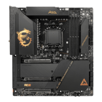
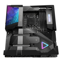
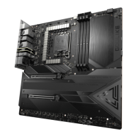
Do you have a question about the MSI MEG X670E GODLIKE and is the answer not in the manual?
Explains the importance of correct case stand-off placement to prevent motherboard damage.
Details how protective paint prevents components from scratching around screw holes.
Offers advice on optimal memory module installation for stability and performance.
Suggests configurations for installing multiple graphics cards in the PCIe slots.
Details the specific steps for installing an M.2 SSD into the M2_1 slot.
Details the front panel audio connector and its pinout.
Explains the front panel connectors for power, reset, LEDs, buzzer, and speaker.
Describes the USB 3.2 Gen 2 Type-C front panel connector.
Explains the USB 3.2 Gen 2x2 Type-C front panel connector for high-speed data transfer.
Details the USB 3.2 Gen 1 connectors for front panel USB ports.
Explains the USB 2.0 connectors for front panel USB ports.
Describes the connectors for attaching thermal sensors to monitor temperatures.
Explains the motherboard's power and reset buttons and their functions.
Explains how to use the JBAT1 jumper to reset BIOS settings.
Discusses the CMOS battery and its role in retaining BIOS settings.
Provides step-by-step instructions for installing Windows 10 or 11.
Details how to install system drivers using the provided MSI USB drive.
Introduces MSI Center and its features for system optimization and control.
Explains how to access the BIOS setup utility during system startup.
Explains different methods to reset the BIOS settings to default values.
Details how to update the BIOS using MSI's M-FLASH utility.
Guides on updating the BIOS using the MSI Center software.
Explains how to update the BIOS using the dedicated Flash BIOS button.
Offers guidance on obtaining technical assistance and resources from MSI.
| Processor socket | Socket AM5 |
|---|---|
| Processor manufacturer | AMD |
| Compatible processor series | AMD Ryzen™ 7 |
| Maximum number of SMP processors | 1 |
| Memory channels | Dual-channel |
| Memory slots type | DIMM |
| Number of memory slots | 4 |
| Supported memory types | DDR5-SDRAM |
| Maximum internal memory | 128 GB |
| Bluetooth | Yes |
| Wi-Fi standards | 802.11a, 802.11b, 802.11g, Wi-Fi 4 (802.11n), Wi-Fi 5 (802.11ac), Wi-Fi 6 (802.11ax), Wi-Fi 6E (802.11ax) |
| Bluetooth version | 5.2 |
| Top Wi-Fi standard | Wi-Fi 6E (802.11ax) |
| Ethernet interface type | 10 Gigabit Ethernet |
| Number of SATA III connectors | 8 |
| HDMI ports quantity | 0 |
| USB 2.0 ports quantity | USB 2.0 ports have a data transmission speed of 480 Mbps, and are backwards compatible with USB 1.1 ports. You can connect all kinds of peripheral devices to them. |
| USB 3.2 Gen 2x2 Type-C ports quantity | 2 |
| USB 3.2 Gen 2 (3.1 Gen 2) Type-A ports quantity | 7 |
| RAID levels | 0, 1, 10 |
| Supported storage drive types | HDD & SSD |
| Supported storage drive interfaces | M.2, SATA II |
| Cables included | SATA |
| BIOS type | - |
| Audio chip | Realtek ALC4082 |
| Component for | PC |
| Motherboard chipset | AMD X670 |
| Audio output channels | 7.1 channels |
| Motherboard form factor | Extended ATX |
| Windows operating systems supported | Windows 10 Home x64, Windows 11 x64 |
| Depth | 304.8 mm |
|---|---|
| Width | 288 mm |
