En-8
MS-7235 Mainboard
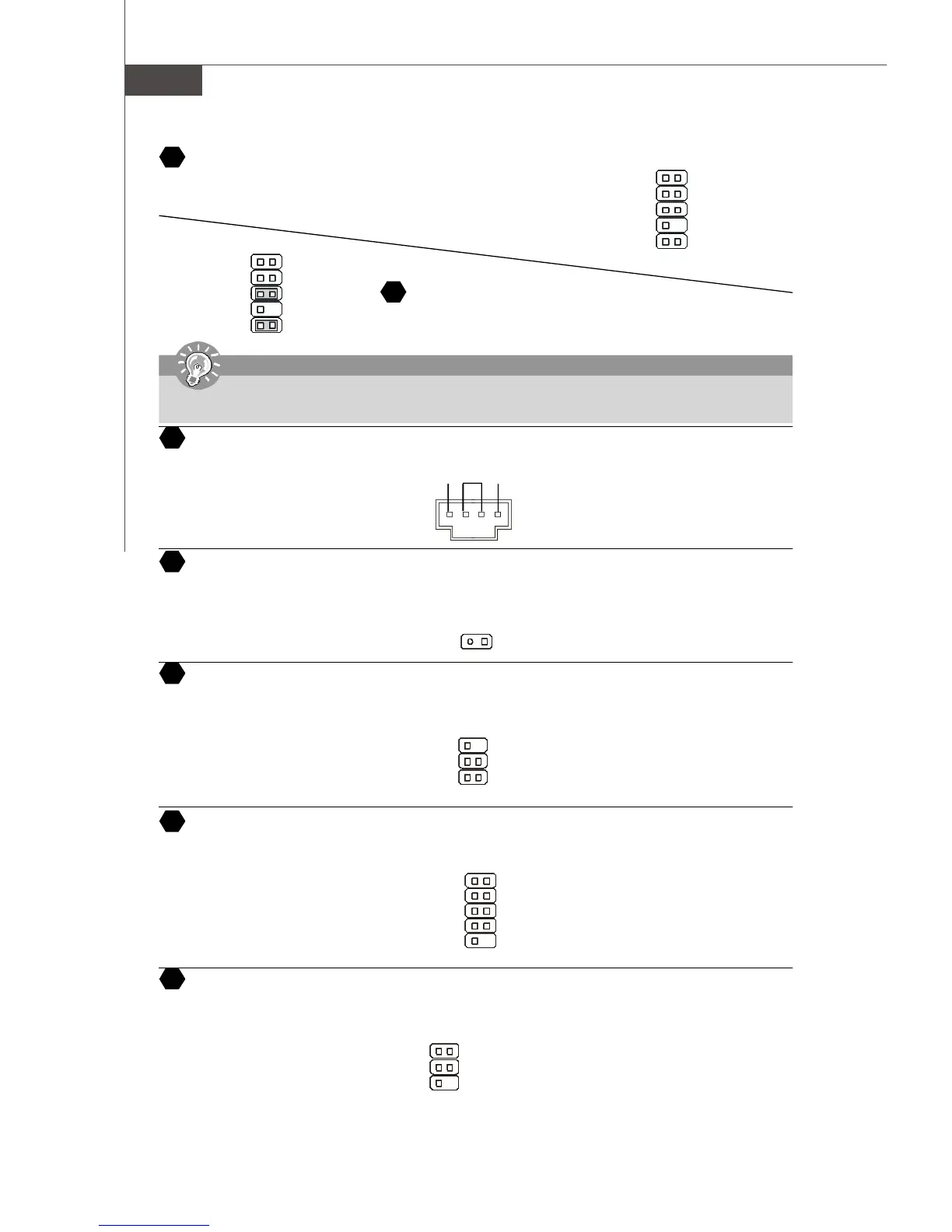
Front Panel Audio Connector
The front panel audio connector allows you to connect to the front panel audio and
is compliant with Intel
®
Front Panel I/O Connectivity Design Guide.
CD-In Connector
This connector is provided for CD-ROM audio.
1
2
910
port1 _L
port1 _R
port2_R
Sense_Send
port2_L
Ground
Presence#
Sense1_Return
Key
Sense2_Return
Chassis Intrusion Switch Connector
This connector is connected to a 2-pin chassis switch. If the chassis is opened, the switch will be short. The system will
record this status and show a warning message on the screen. To clear the warning, you must enter the BIOS utility and
clear the record.
IrDA Infrared Module Connector
The connector allows you to connect to IrDA Infrared module. You must configure the setting through the BIOS setup to use
the IR function. It is compliant with Intel
®
Front Panel I/O Connectivity Design Guide.
Serial Port Header
The 9-pin header allows you to connect serial port via an external COM port bracket.
1
CINTRU
2
Ground
1
5
6
DCD
SIN
SOUT
DTR
Ground
DSR
RTS
CTS
RI (9)
TV-Out Connector
The TV-Out connector is for you to attach a TV-Out bracket. The TV-Out bracket offers some types of TV-Out connectors.
Select the appropriate one to connect to an television and it will be able to display PC information.
3
1 4
Ground
Yout
Cout
COMP or CVBS
Ground (5)
GND R
L
Front Panel Audio Connector
The front panel audio connector allows you to connect to the front panel
audio and is compliant with Intel
®
Front Panel I/O Connectivity Design Guide.
1
2
910
AUD_MIC
AUD_MIC_BIAS
AUD_FPout_R
HP_ON
AUD_FPout_L
AUD_GND
AUD_VCC
AUD_RET_R
Key
AUD_RET_L
12
13
14
15
16
17
18
6
5
2
1
NC
VCC5
IRTX
NC
Ground
IRRX
Important
If you do not want to connect to the front audio header, pins 5 & 6, 9 & 10 have to be jumpered in order to have signal output
directed to the rear audio ports. Otherwise, the Line-Out connector on the back panel will not function.