Do you have a question about the MSI P35 Neo series and is the answer not in the manual?
States the intellectual property rights and content guarantees of the document.
Lists trademarks and acknowledges their respective owners.
Details of document revisions and release dates.
Provides information on obtaining technical support and accessing online resources.
Essential guidelines for safe installation and operation of the equipment.
Caution regarding explosion risk if battery is replaced incorrectly.
Addresses potential radio interference and waste battery disposal.
Statement on compliance with FCC limits for Class B digital devices.
Measures to correct radio or television reception interference.
Requirement for using shielded interface cables and AC power cord.
MSI's commitment to EU Directive 2002/96/EC for product take-back.
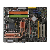
Overview of the P35/G33 Neo Series mainboard and its features.
Details on supported CPU types and socket.
Supported Front Side Bus frequencies.
Information on North and South bridge chipsets.
Details on supported DDR2 memory types and capacity.
Details on LAN, IEEE 1394, Audio, IDE, SATA, and RAID controllers.
Details on the floppy disk drive connector.
Description of ports on the rear I/O panel.
Description of internal headers for front panel connections.
Details on PCI Express and PCI slots.
Mainboard physical dimensions (ATX) and mounting holes.
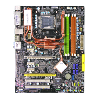
Visual diagram showing the placement of major components on the mainboard.
List and images of items included in the product package.
Important notes and warnings for hardware installation procedures.
Diagram identifying key components with corresponding page numbers for details.
Information on CPU support, installation, and cooler requirements.
Critical advice on overheating, CPU replacement, and overclocking.
Details on LGA 775 CPU orientation and thermal paste application.
Detailed instructions for installing the CPU and CPU cooler correctly.
Essential checks to ensure correct CPU installation and socket protection.
Details on DDR2 memory module specifications and compatibility.
Guidelines for installing memory modules for dual-channel operation.
Step-by-step guide for inserting memory modules into DIMM slots.
Crucial notes on DDR2 compatibility and dual-channel installation.
Description and pin definition for the ATX 24-pin power connector.
Description and pin definition for the ATX 12V CPU power connector.
Recommendations for proper power supply connection and wattage.
Connects PS/2 mouse and keyboard.
Standard printer port supporting EPP/ECP modes.
High-speed serial port for communication devices.
DB15-pin female connector for monitor output.
IEEE1394 port for connecting compatible devices.
Universal Serial Bus ports for peripherals.
RJ-45 jack for network connection with LED indicators.
Color-coded jacks for different audio sound effects.
Details for connecting a floppy disk drive.
Details for connecting IDE devices.
Note on configuring IDE devices with jumpers for master/slave modes.
Description of SATA connectors and their controllers.
Warning about folding Serial ATA cables to avoid data loss.
Details on fan power connectors (CPUFAN1, SYSFAN1, SYSFAN2).
Description of the chassis intrusion switch connector.
Description of the CD-in audio input connector.
Pinout for the HD Audio front panel connector.
Pinout for the AC'97 audio front panel connector.
Description and pin definition for front USB connectors.
Warning about connecting VCC and GND pins correctly for USB.
Connector for digital audio transmission via S/PDIF.
Connector for IEEE1394 devices via an optional bracket.
Pin definition for the front panel power and HDD LED connector.
Pin definition for the front panel speaker and Buzzer connector.
Instructions for clearing CMOS settings using the JBAT1 jumper.
Warning about clearing CMOS while the system is on.
Details on PCI Express slot specifications and transfer rates.
Details on PCI slot compatibility for add-on cards.
Precautions for installing and removing expansion cards.
Explanation of PCI interrupt request routing.
Overview of the BIOS Setup program and its purpose.
Instructions on how to enter the BIOS setup menu using the DEL key.
Explanation of the BIOS version format and its components.
List of keys used for navigating and selecting items in BIOS setup.
How to access help screens within the BIOS setup.
Menu for basic system configurations like date and time.
Menu for advanced system features and settings.
Menu to configure integrated hardware peripherals.
Menu for configuring power management settings.
Menu for Plug and Play and PCI configurations.
Menu to display PC health status.
Menu for frequency and voltage adjustments.
Option to load stable default BIOS settings for stability.
Option to load optimal factory default BIOS settings for performance.
Option to set a BIOS password for security.
Option to save changes and exit BIOS setup.
Option to exit BIOS setup without saving changes.
How to set the system date and time.
Display of connected SATA device information.
Setting for the installed floppy drive type.
Display of CPU, BIOS, and memory status.
Option to enable or disable LBA Mode for hard drives.
Option to select DMA Mode for devices.
Enabling S.M.A.R.T. for hard disk monitoring.
Note on BIOS detection of IDE/SATA devices controlled by Marvell.
Enables protection against BIOS corruption.
Option to display the company logo during boot.
Speeds up the boot process by skipping checks.
Sets the Num Lock status on system startup.
Enables or disables the APIC controller for IRQ resources.
Selects the MPS version for the operating system.
Settings for Execute Disable Bit and CPUID MaxVal.
Settings for HPET and VGA Share Memory Size.
Defines the order of devices for system boot-up.
Sets the primary boot device sequence.
Allows booting from alternative devices if primary fails.
Enable/disable the onboard USB controller.
Enables USB device support in the operating system.
Enable/disable the onboard LAN controller.
Decides whether to invoke the LAN controller's Boot ROM.
Enable/disable the onboard IEEE1394 controller.
Enable/disable the onboard audio controller.
Enables/disables PCI busmastering for IDE drives.
Specifies the operating mode for SATA devices.
Configure COM port, Parallel Port, and Parallel Port Mode.
Activates the ACPI function for power management.
Specifies ACPI power saving modes (S1/S3).
Initializes VGA BIOS upon system resume from S3.
Sets time before system enters suspend mode.
Configures the power button behavior (Off/Suspend).
Specifies system behavior after AC power interruption.
Enables system wake-up from S3 sleep via USB, PS/2, or RTC.
Enables PS/2 mouse input to wake system from S3.
Allows waking system via PCI Power Management Events.
Allows waking system via PCI Express events.
Enables system boot-up on a scheduled time/date.
Selects the primary graphics adapter for boot.
Controls PCI device bus access time.
Specifies the IRQ line for PCI slots.
Manages IRQ resource allocation for devices.
Specifies bus usage for IRQ lines.
Explanation of IRQ signaling between devices and the OS.
Enables/disables chassis intrusion detection and warning.
Configures CPU fan speed based on target temperature.
Sets tolerance for CPU fan speed adjustments.
Displays current status of hardware devices like temperatures and fan speeds.
Shows current CPU and DRAM clock speeds.
Automatic CPU frequency adjustment technology.
Manages processor performance level based on system load.
Selects the CPU Front Side Bus clock frequency.
Settings for DRAM timings and configuration.
Sets CAS latency for DRAM timing.
Sets timing delay between CAS and RAS strobe signals.
Controls cycles for Row Address Strobe precharge.
Controls cycles for Row Address Strobe precharge.
Controls the CPU FSB/DRAM Clock Ratio.
Selects the PCI Express frequency.
Disables clocks for empty slots to reduce EMI.
Allows increasing the CPU voltage.
Adjusts memory voltage for DDR speed.
Adjusts the North Bridge chipset voltage.
Adjusts the South Bridge I/O voltage.
Adjusts the South Bridge core voltage.
Sets the FSB VTT voltage.
Enables/disables Spread Spectrum for EMI reduction.
Advice on using Spread Spectrum for stability and overclocking.
Restores stable default BIOS settings for minimal performance.
Restores optimal factory default BIOS settings for performance.
Instructions for setting and clearing a BIOS password.
Introduction to MSI's utility for monitoring and configuring hardware status.
System requirements for installing the Dual CoreCenter utility.
How to activate Dual Core Center via system tray, desktop, or start-up menu.
Conditions for activating full utility functions with specific MSI graphics cards.
Overview of the main interface and its buttons.
Accessing mainboard/graphics status and overclocking.
Predefined settings for different operating environments.
Choosing between smooth or quick optimal value adjustments.
Adjusting and monitoring system clock, voltage, fan speed, and temperature.
Saving and managing custom settings profiles.
How DOT automatically adjusts CPU/GPU frequency and fan speed.
Using rate buttons to select DOT level and apply.
Risk warning and advice for using Dynamic Overclocking Technology.
Viewing clock status and selecting values for overclocking.
Using plus/minus signs for clock adjustments and apply/cancel/default buttons.
Displaying graphs of system clock speeds.
Note on saving clock changes in user profiles vs. default profile.
Viewing voltage status and selecting values for overclocking.
Using plus/minus signs for voltage adjustments and apply/cancel/default buttons.
Displaying graphs of system voltages.
Note on saving voltage changes in user profiles vs. default profile.
Reading fan status and adjusting fan speeds.
Using plus/minus signs for fan speed adjustments and default button.
Displaying graphs of system fan speeds.
Notes on disabling BIOS fan control and saving fan speed profiles.
Monitoring system temperatures for VGA and motherboard components.
Displaying graphs of system temperatures.
Selecting and managing user-defined profiles.
Setting clock, fan speed, and voltage for profiles.
Using draw bars to set max temperature and min fan speed.
Saving profile name and changes.
Selecting and loading user profiles.
Description of Realtek ALC888 audio codec capabilities.
Steps for installing the Realtek HD Audio driver on Windows.
Steps for proceeding through the driver installation wizard.
Option to restart the system after driver installation.
How to open the HD Audio Configuration utility.
Enabling the audio driver via the Control Panel.
Selecting sound effects and environments for audio playback.
Adjusting equalizer settings and saving presets.
Using the equalizer tool to customize sound settings.
Save, Reset, Enable/Disable, Load, Delete equalizer settings.
Optimized equalizer settings for quick enjoyment.
Using Karaoke mode for vocal cancellation and key adjustment.
Adjusting speaker volumes for rear and front panels.
Enabling simultaneous playback of multiple audio sources.
Ensuring playback devices are properly connected.
Selecting audio output ports for playback.
Setting up multi-stream playback for simultaneous audio sources.
Controlling playback devices and muting volume controls.
Selecting volume controls to display and enabling multi-streaming.
Selecting the input device for recording.
Muting sound input and selecting recording volume controls.
Enabling simultaneous recording from multiple channels.
Note on simultaneous recording from CD, Line, Mic, Stereo Mix.
Configuring multi-channel audio and speaker outputs.
Connecting speakers and detecting plugged-in devices.
Options for front panel jack detection.
Mutes rear panel output when front headphone is plugged in.
Enables automatic popup dialogue when device is plugged in.
Configuring S/PDIF output sampling rate.
Selecting the source for S/PDIF digital audio output.
Testing individual speakers or using auto-test.
Reducing noise during microphone recording.
Preventing playback sound from being recorded with microphone input.
Adjusting 3D audio for gaming and selecting environments.
Displaying driver version, DirectX, controller, and codec details.
Managing the audio icon and accessing multimedia features.
Connecting speakers according to selected multi-channel audio mode.
Diagram and caption for 2-channel speaker connections.
Diagram and caption for 4-channel speaker connections.
Diagram and caption for 6-channel speaker connections.
Diagram and caption for 8-channel speaker connections.
| Brand | MSI |
|---|---|
| Model | P35 Neo series |
| Category | Motherboard |
| Language | English |