2-13
Hardware Setup
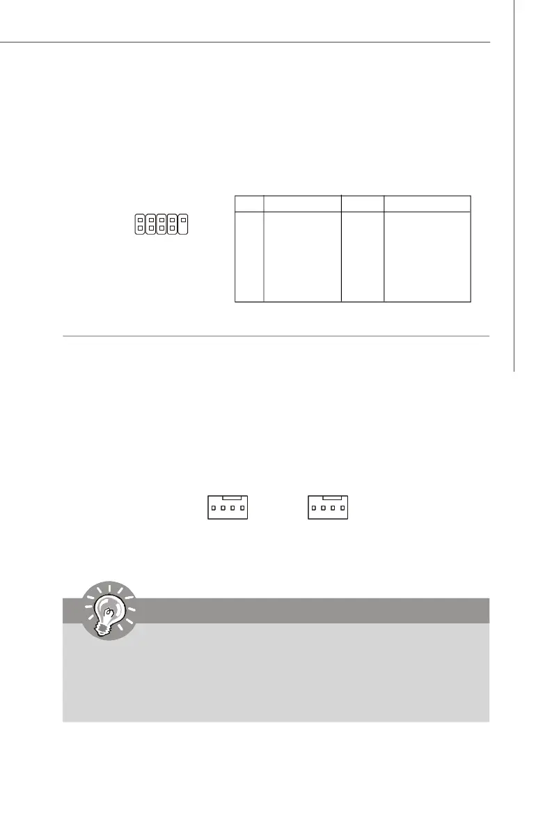
Fan Power Connectors: CPU_FAN1, SYS_FAN
The fan power connectors support system cooling fan with +12V. When connecting
the wire to the connectors, always take note that the red wire is the positive and
should be connected to the +12V, the black wire is Ground and should be connected
to GND. If the mainboard has a System Hardware Monitor chipset on-board, you must
use a specially designed fan with speed sensor to take advantage of the CPU fan
control.
CPU_FAN1
SENSOR
+12V
GND
CONTROL
Important
1.Please refer to the recommended CPU fans at Intel
®
/ AMD
®
official website
or consult the vendors for proper CPU cooling fan.
2.CPUFAN1 supports fan control. You can install Core Center utility (refer to
Appendix for details) that will automatically control the CPU fan speed
according to the actual CPU temperature.
SYS_FAN
SENSOR
+12V
GND
CONTROL
IEEE 1394 Connector: JFW1 (Optional)
The mainboard provides an IEEE1394 pinheader that allows you to connect IEEE 1394
ports via an external IEEE1394 bracket (optional).
Pin Definition
PIN SIGNAL PIN SIGNAL
1 TPA+ 2 TPA-
3 Ground 4 Ground
5 TPB+ 6 TPB-
7 Cable power 8 Cable power
9 Key (no pin) 10 Ground
JFW1
1
2
9
10
 Loading...