MTD Engine - Series 350/450/650
35
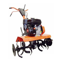
12.13.For inspection purposes, the valve retainers can
be removed with light finger pressure.
See Figure 12.13.
12.14.Only the intake valve has a valve guide seal.
See Figure 12.14.
NOTE: Outside of warranty, the dealer may
choose to recondition a cylinder head.
• Replacement valve guides are not presently
available.
• Valve spring free length should be at least 1.22”
(28.5mm). Original length is 1.44” (36.6mm).
• Valve seats are 45 degrees, with a 15 degree
topping cut and a 75 degree narrowing cut.
• Seat width should be .043”-.050” (1.1-1.3mm)
with a margin of .024” (.6mm) on the exhaust
valve and .027” (7mm) on the intake valve.
Figure 12.13
Figure 12.14
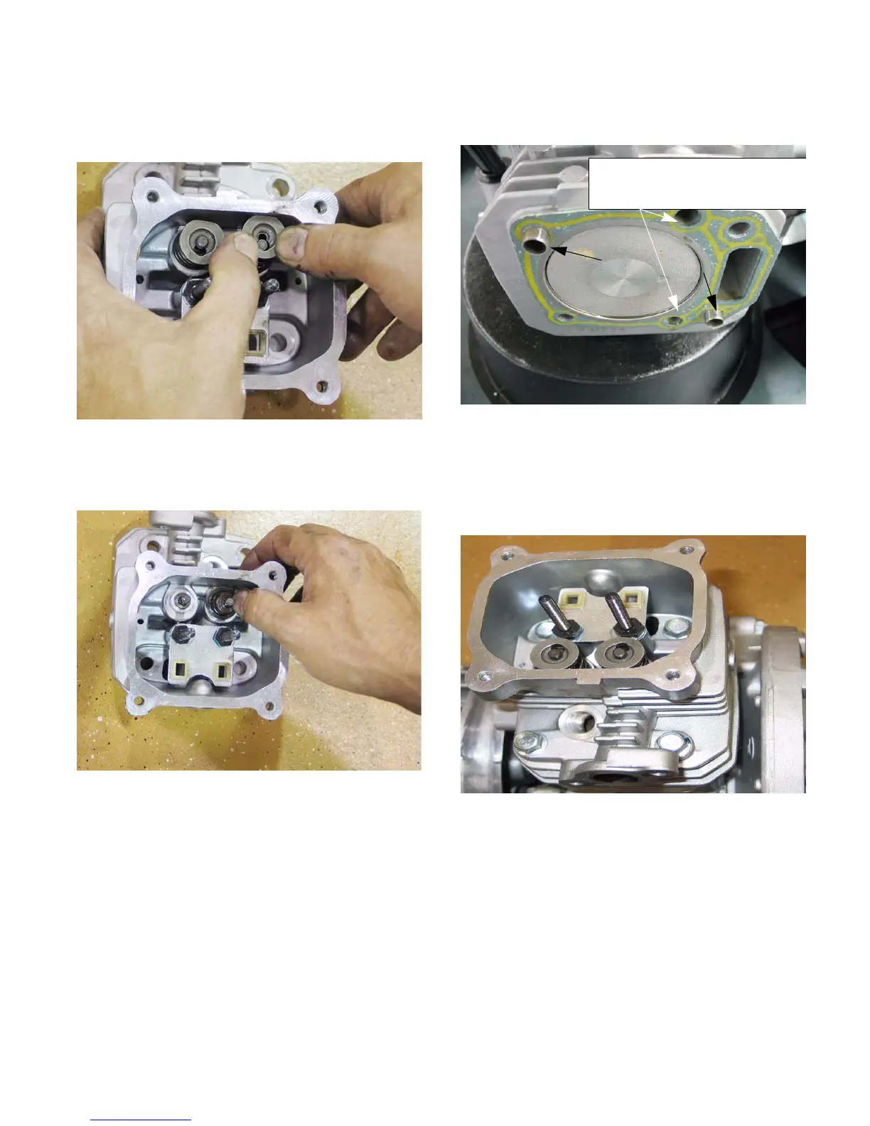
12.15.Position new cylinder head gasket and dowels
on engine block. See Figure 12.15.
12.16.Position the cylinder head on the engine block.
12.17.Install the 4 head bolts, and tighten them to a
step torque of 212 in-lb. (24 Nm) in an alternat-
ing diagonal pattern. See Figure 12.17.
12.18.Insert the push rods.
12.19.Install and adjust the rocker arms as described
in steps 5.13 through 5.29 of the MAINTE-
NANCE AND ADJUSTMENT section of this
manual.
12.20.Install the fuel and exhaust systems, using new
gaskets, as described in the FUEL SYSTEM and
EXHAUST SYSTEM sections of this manual.
12.21.Test run the mower in a safe area before return-
ing it to service. Check all safety features.
Figure 12.15
Dowel
Dowel
NOTE: There is a right way and a
wrong way to install the head
gasket: holes should match
Figure 12.17
4
3
2
1
www.mymowerparts.com
For Discount White Outdoor Parts Call 606-678-9623 or 606-561-4983
 Loading...