MTD Engine - Series 350/450/650
8
5.38. Interpreting compression readings:
• Near Zero (< 20PSI [1.38 Bar]): most likely a
stuck valve or too-tight valve lash, provided
starter rope pulls with normal effort.
• Moderately low (20-45 PSI [1.38 - 3.1Bar]):
Valve seat damage or piston ring wear.
Leak-down test or compressed-air test will help
confirm if damage is isolated to valves or piston
rings.
Oil smoke in exhaust on throttle increase tends
to indicate piston ring wear.
Oil smoke in exhaust on over-run tends to indi-
cate valve guide wear.
• Too high compression (>95 PSI [>6.55 Bar])
most likely indicates excessive valve lash,
negating the automatic compression release. It
may also indicate a partial hydraulic lock or
severe carbon deposits within the cylinder.
5.39. Stop switch and brake: The stop switch and
brake must be able to stop the blade from rotat-
ing within 3.0 seconds after the release of the
safety bail, per ANSI B71.1-2003 standard.
5.40. Make sure that the mower conforms to these
standards by performing a stop test.
5.41. Check the movement of the cable and brake
mechanism. See Figure 5.41.
• The cable should not bind. Replace the cable if
it is kinked, melted frayed, or damaged in any
other way that causes it to bind.
• The brake arm on the engine should not bind.
• Each can be lubricated with light penetrating oil
or a dry PTFE-based lubricant such as “Tri-Flow”
dry Teflon lubricant.
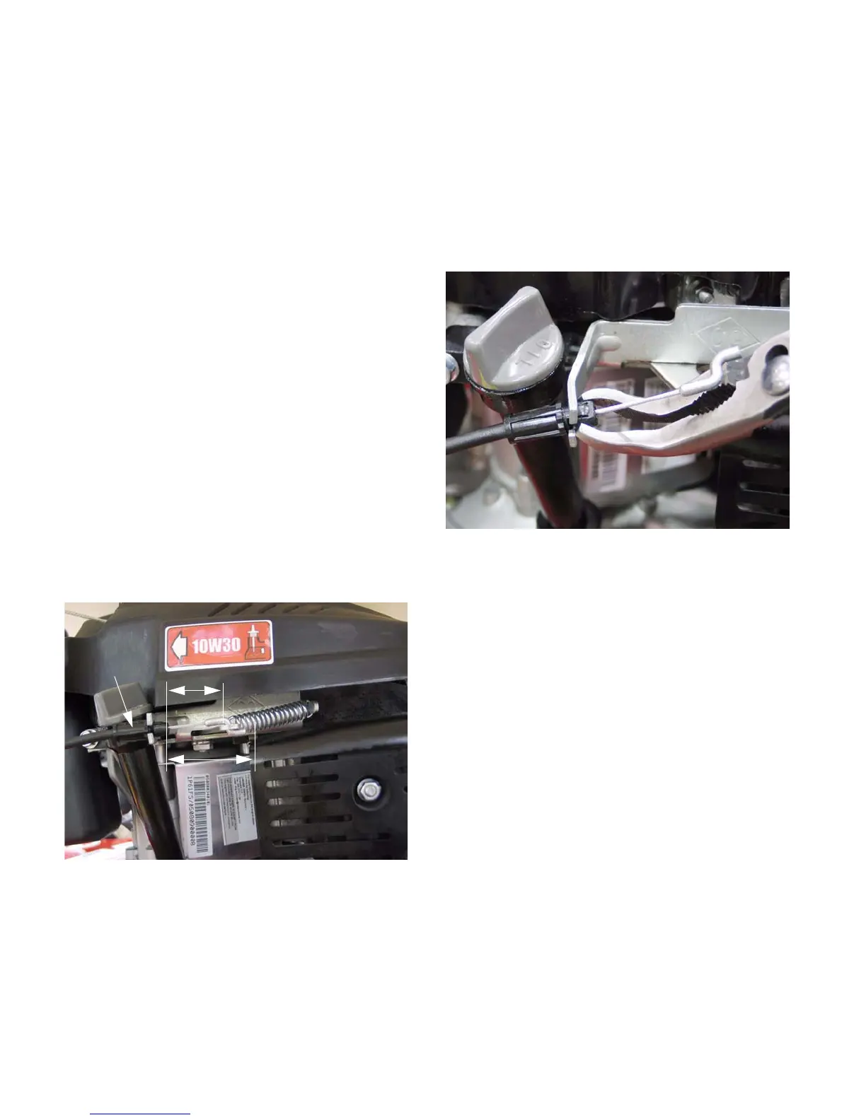
5.42. To replace the cable: See Figure 5.42.
• Squeeze the safety bail ends together to release
the bail from the upper handle bar.
• Releasing the bail from the handle bar will pro-
vide enough slack in the cable to unhook the Z-
fitting at the top of the cable from the bail.
• After the bail end of the cable is unhooked, the
Z-fitting at the engine end of the cable can be
unhooked.
• Squeeze the barbs together at the engine end of
the cable housing to disconnect it completely
from the engine.
• Remove the nut and bolt that secure the cable to
the handle bar.
• Reverse the removal process to install the cable,
then test the mower in a safe area before return-
ing it to service.
5.43. The brake pad should be replaced when the
thickness of the friction material is less than .25”
(6.35mm) at the thinnest spot.
Figure 5.41
Safety bail in RUN position
Safety bail in OFF position
Engine control
cable
Figure 5.42
Releasing the engine control
cable from the bracket
www.mymowerparts.com
For Discount White Outdoor Parts Call 606-678-9623 or 606-561-4983
 Loading...