MTD Engine - Series 350/450/650
7
5.21. Intake valve lash (top valve) should be .003”-
.005” (.10 +
.02mm).
5.22. Exhaust valve lash (bottom valve) should be
.005-.007” (.15 +
.02mm).
5.23. Use a 10mm wrench to loosen the jam nut, and
a 14mm wrench to adjust the rocker arm fulcrum
nut. See Figure 5.23.
• Tighten the rocker arm fulcrum nut to close-up
the clearance between the end of the valve stem
and the contact point on the rocker arm.
• Loosen the rocker arm fulcrum nut to open-up
the clearance between the end of the valve stem
and the contact point on the rocker arm.
5.24. Hold the fulcrum nut with a 14mm wrench,
tighten the jam nut to a torque of 88.5 in-lb.
(10Nm) using a 10mm wrench.
5.25. Double-check the clearance after tightening the
jam nut, to confirm that it did not shift. Re-adjust
if necessary.
5.26. Rotate the engine through several compression
cycles:
• Observe the movement of the valve train.
• Return the piston to TDC compression stroke
and re-check the valve lash to confirm consistent
movement of the valve gear, including the slight
bump to the exhaust valve from the automatic
compression release.
5.27. Clean-up any oil around the valve cover open-
ing, clean the valve cover, replace the valve
cover gasket if necessary.
Figure 5.23
Setting intake valve lash
5.28. Install the valve cover, tightening the valve cover
screws to a torque of 71 in-lb (8 Nm).
5.29. Install the spark plug and tighten to a torque of
177-221 in-lbs (20 - 25 Nm).
5.30. Release the spring clamp securing the safety
bail, start the engine and test run it long enough
to confirm correct operation.
5.31. Compression should be in the range of 70 +
25
PSI (5.2 +
1.7 Bar).
5.32. If the engine has been run, allow it to cool thor-
oughly.
5.33. Disconnect the high-tension lead from the spark
plug and ground it well away from the spark plug
hole. See Figure 5.16.
5.34. Remove the spark plug using a 13/16” or 21mm
wrench. A flexible coupling or “wobbly” exten-
sion may help.
5.35. Hold the safety bail and pull the starter rope sev-
eral times to purge any fuel or oil from the com-
bustion chamber.
NOTE: Air compresses readily, liquid does not.
Liquid in the combustion chamber will result in
an artificially high compression reading.
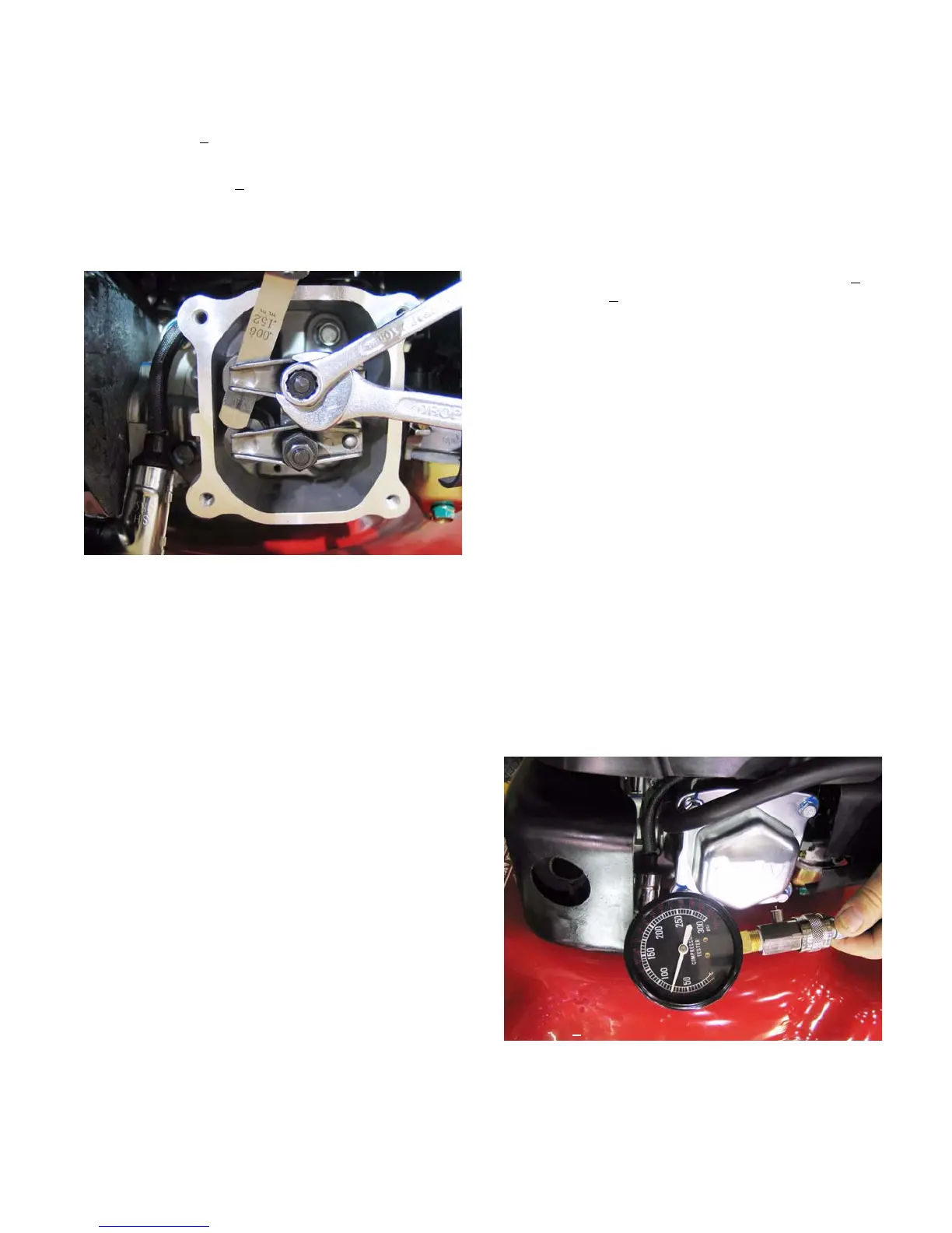
5.36. Install a compression gauge in the spark plug
hole.
5.37. Confirm that the gauge is “zeroed”, then hold the
safety bail and pull the starter rope repeatedly,
until the needle on the gauge has risen as far as
it is going to. See Figure 5.37.
Figure 5.37
Compression gauge
Reading ~
90 PSI
www.mymowerparts.com
For Discount White Outdoor Parts Call 606-678-9623 or 606-561-4983
 Loading...