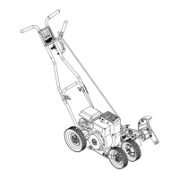
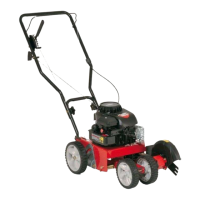
3. Tooperatetheunitasatrimmer, move the adjust-
ment lever and rotate the cutting blade 90°. See
figure 8. Move the front wheels all the way to the
right, as described in the Control section.
WARNING: Do not the blade
adjust guard
with the engine running.
LUBRICATION
Wheels--The wheels are plastic and require no lubri-
cation.
Cutting Head Bearings--The two ball bearings in the
cutting head are lubricated and sealed at the factory
and require no lubrication• Lubricate all other moving
parts with engine oil.
Shaft--Lubricate the two bearings and under the com-
pression spring on the shaft with light oil frequently
during the season. See figure 11.
Engine--Refer to engine manual for lubrication
instructions•
Up to Fence, Foundations, etc..
FIGURE 8.
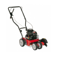
4. Units equipped with curb wheel only: To edge
along a curb, remove the hairpin clipfrom the right
side of the front axle, slide the right wheel toward
the left side of the unit and replace the hairpin clip.
See figure 9. Lower the right rear wheel by moving
the height adjustment lever toward the engine,
pivoting the wheel to the desired depth and
releasing the lever. See figure 10.
FIGURE 9._ptional Curb Wheel
Height Adjustment Lever
FIGURE 10._ptional Curb Wheel
MAINTENANCE
WARNING: Disconnect the spark plug
wire and ground against the engine
before performing any adjustment,
repairs or maintenance.
ENGINE
Refer to engine manual for complete instructions for
care and maintenance of engine•
BLADEREMOVAL
Use a wrench on both sides of the blade to remove it
for replacement•
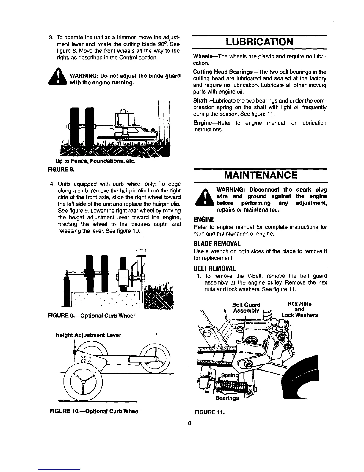
BELTREMOVAL
1. To remove the V-belt, remove the belt guard
assembly at the engine pulley. Remove the hex
nuts and lockwashers. See figure 11.
Belt Guard
Hex Nuts
and
Lock Washers
Bearings
FIGURE 11.
6