Maintenance & Adjustments
6
13
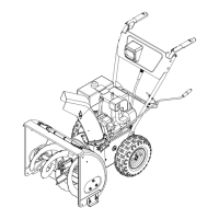
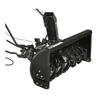
Shave Plate and Skid Shoes
The shave plate and skid shoes on the bottom of the snow
thrower are subject to wear. These should be checked
periodically and replaced when necessary.
To replace skid shoes:
1. Remove the carriage bolts and nuts securing each skid shoe
to the auger housing, See Fig. 6-1.
2. Reassemble new skid shoes with hardware just removed.
Make sure the skid shoes are adjusted to be level.
To remove shave plate:
3. Remove both skid shoes and hardware including carriage
bolts and nuts which attach shave plate to the snow
thrower housing. For location of shave plate, see Fig. 6-1.
4. Reassemble new shave plate, making sure heads of the
carriage bolts are to the inside of the housing.
5. Reinstall skid shoes. Tighten securely.
Maintenance
General Recommendations
Always observe safety rules when performing any type of •
maintenance.
The warranty on this snow thrower does not cover items •
that have been subjected to operator abuse or negligence.
To receive full value from the warranty, operator must
maintain the snow thrower as instructed in this manual.
Periodically check all fasteners and hardware to make sure •
these are tight.
WARNING! Before servicing, repairing, lubricating,
or inspecting, disengage all controls and stop
engine. Wait until all moving parts have come to a
complete stop. Disconnect spark plug wire and
ground it against the engine to prevent unintended
starting. Always wear safety glasses during
operation or while performing any adjustments or
repairs.
Engine
IMPORTANT: Refer to the engine operator’s manual included
with the snow thrower for complete maintenance instructions.
Tire Pressure
Refer to “Assembly & Set-Up” section of this manual.
Check V-Belts
Follow instructions below to check condition of drive belts every
50 hours of operation.
1. Remove the plastic belt cover on the front of the engine by
removing the self-tapping screw and pressing the plastic
tabs to release the belt cover. See Fig. 7-1 in the Service
section of this manual.
2. Visually inspect for frayed, cracked, or excessively worn out
belts. Replace, if necessary, following instructions in the
Service section of this manual.
Figure 6-1
Note: Augers not shown for clarity.
 Loading...