Matrix
®
E-Series Technical Reference Manual 380V – 480V
Form: MAE-TRM-E September 2020 REV. 001 10
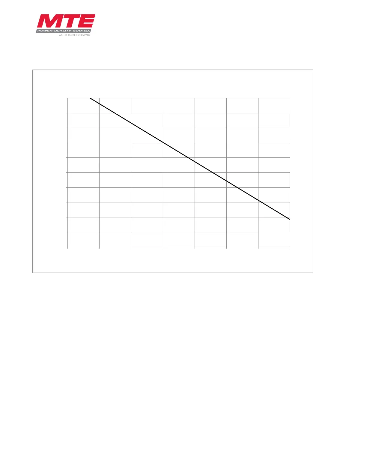
Voltage Distortion Derating
Figure 3-4: Voltage Distortion Derating Curve
This plot assists in proper de-rating of a Matrix E-Series harmonic filter in environments with a
preexisting voltage distortion. Example: In a system with 10% voltage distortion, a Matrix filter
will need to be oversized by 5.5% to obtain the same performance as an appropriate filter in a
0% distortion environment.
0.9
0.91
0.92
0.93
0.94
0.95
0.96
0.97
0.98
0.99
1
0 2 4 6 8 10 12 14
Derating Factor
Voltage Distortion [%]
Voltage Distortion Derating Curve