Sine Wave 2-8 kHz Series A Filter
15 Part No. INSTR-020 REL. 080310
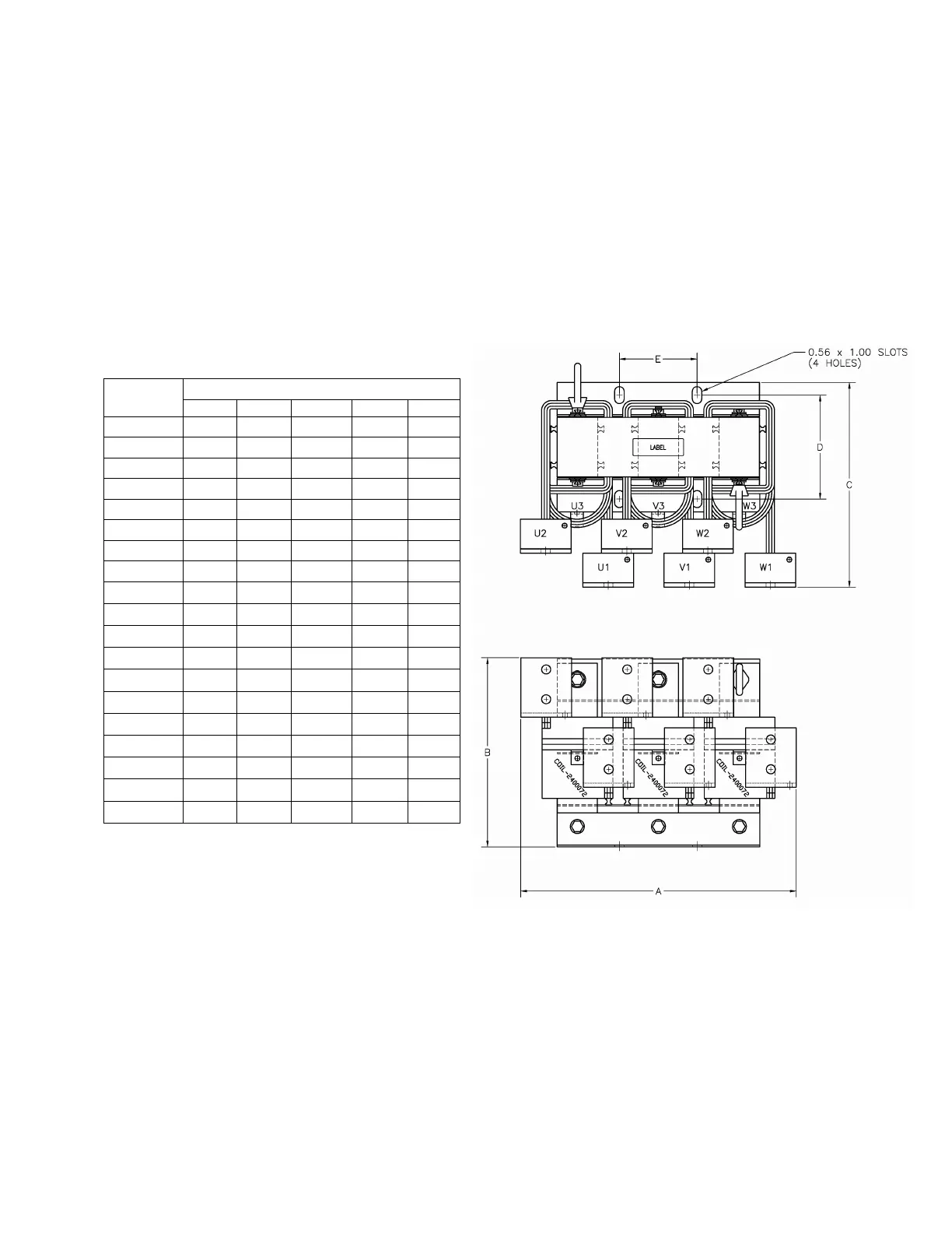
Sine Wave Filters rated 80 amps through 720 amps are made up of a reactor and a
RC panel. These components are designed to be mounted vertically within an
appropriate enclosure. The reactor generates heat and should be mounted away
from components affected by heat. Align the reactor to allow cooling air to flow
through it. A filter showing correct reactor alignment and placement is shown in
figure 6. The RC panel should be located in the lowest temperature regions of the
enclosure – generally toward the bottom. An example of an MCC application is
shown in Figure 7
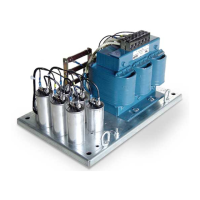
Table 4
FIG. A
DIMENSIONS Inches
Figure
A (W) B (H) C (D) D E
A1
14.4 13 10.5 8.75 4.6
A2
14.4 13 10.75 8.75 4.6
A3
14.4 13 11.25 8.75 4.6
A4
14.4 13 11.5 9.25 4.6
A5
14.4 13 12.25 9.75 4.6
A6
14.4 13 13.5 10.75 4.6
A7
14.4 13 15 11.75 4.6
A8
22 17 12.5 6.7 7.2
A9
22 17 13.5 7.7 7.2
A10
22 17 15.5 8.2 7.2
A11
22 17 17 9.7 7.2
A12
22 17 15.5 9.7 7.2
A13
22 17 22 12.2 7.2
A14
22 17 17.75 11.2 7.2
A15
33.5 28.5 19.5 12.5 11
A16
33.5 28.5 20 12.5 11
A17
9 6.9 8.1 4.7 4.3
A18
14 13 11.8 6.7 7.2
A19
11 8.8 9.8 4.8 5.6
 Loading...