Temposonics
®
E-Series CANopen
Operation Manual
15
NOTICE
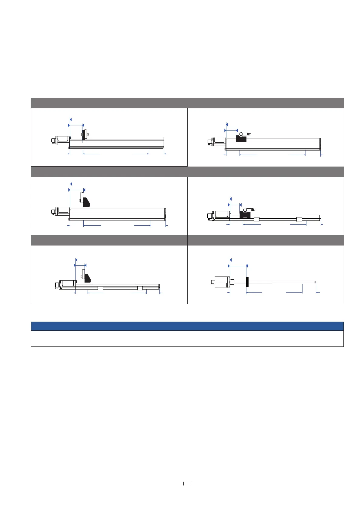
On all sensors, the areas left and right of the active stroke length are provided for mounting and damping of the measuring signal.
They should not be used for measurement, but the active stroke length can be exceeded.
Active measuring range
The technical data of each sensor is checked as well as documented and the active stroke length (useful electrical stroke) with its start and end
position is adjusted during final inspection and testing.
Temposonics
®
E-Series EP with U-magnet Temposonics
®
E-Series EP with magnet slider
68
(2.68)
35
(1.38)
35
(1.38)
Stroke length
Start position
Reference edge of mounting
68
(2.68)
35
(1.38)
19
(0.75)
Stroke length
Start position
Reference edge of mounting
Temposonics
®
E-Series EP with block magnet Temposonics
®
E-Series EL with magnet slider
68
(2.68)
35
(1.38)
35
(1.38)
Stroke length
Start position
Reference edge of mounting
68
(2.68)
35
(1.38)
19
(0.75)
Stroke length
Start position
Reference edge of mounting
Temposonics
®
E-Series EL with block magnet Temposonics
®
E-Series EH with ring or U-magnet
68
(2.68)
35
(1.38)
35
(1.38)
Stroke length
Start position
Reference edge of mounting
63.5
(2.5)
51
(2.01)
51
(2.01)
Start position
Reference edge of mounting
Stroke length
Fig. 14: Active measuring range
Controlling design dimensions are in millimeters and measurements in ( ) are in inches

 Loading...


