I 6 I
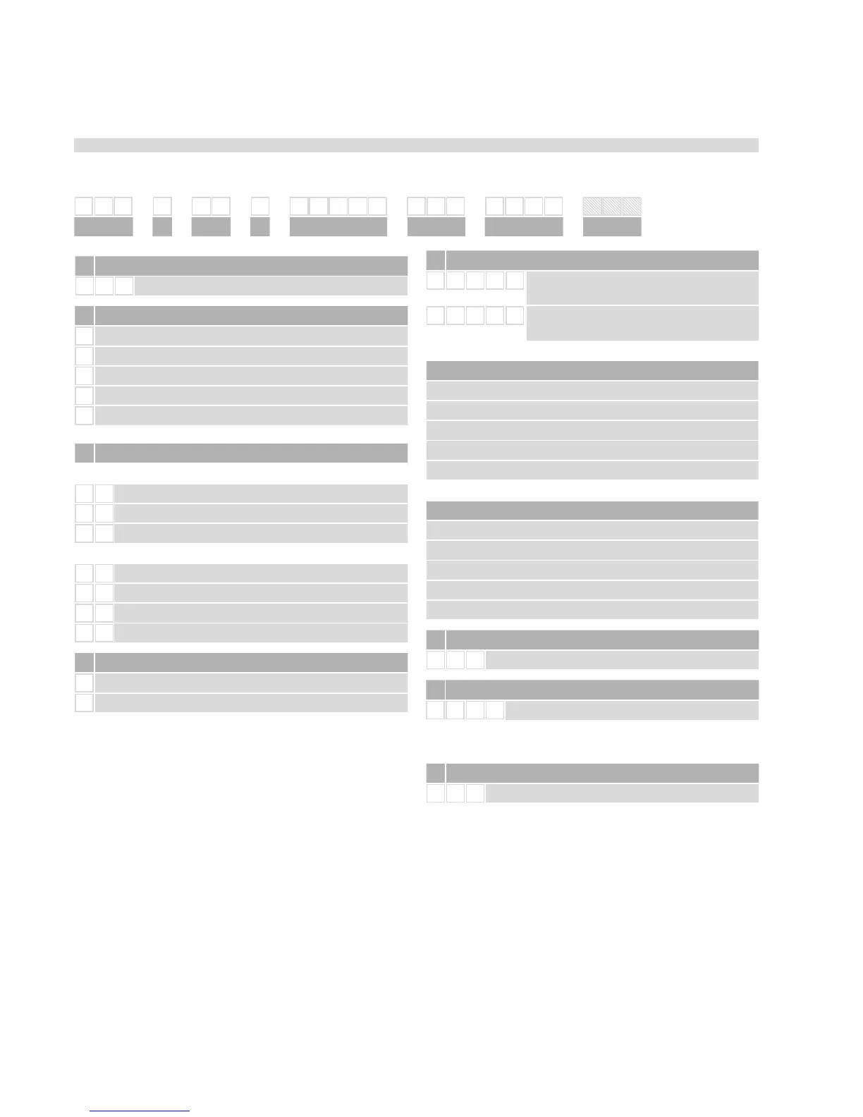
3.3 Order structure of R-Series RD4
Temposonics
®
order code
b Design
S
Pressure fit flange
M
Threaded flange M18×1.5-6g, AF23
C
Threaded flange M18×1.5-6g, AF46
T Threaded flange ¾“–16UNF–3A.
D Threaded flange ¾“–16UNF–3A.
d Sensor electronics
S
Side cable entry
B
Bottom cable entry
a Sensor model
R D
4
Detachable sensor electronics
c Integral cable of sensor rod
For side cable entry:
D 1 PUR-cable, length 250 mm (9.8 in.)
D 2 PUR-cable, length 400 mm (15.7 in.)
D 3 PUR-cable, length 600 mm (23.6 in.)
For bottom cable entry:
R 2 Single wires with flat connector, length 65 mm (2.6 in.)
R 4 Single wires with flat connector, length 170 mm (6.7 in.)
R 5 Single wires with flat connector, length 230 mm (9.1 in.)
R 6 Single wires with flat connector, length 350 mm (13.8 in.)
*/ Non Standard stroke lengths are available; must be encoded in 5 mm / 0.1 in. increments
5/ Note: Please specify magnet numbers for your sensing application and order separately
Standard stroke length (mm)*
Stroke length Ordering steps
25 … 500 mm 5 mm
500 … 750 mm 10 mm
750…1000 mm 25 mm
1000…2500 mm 50 mm
2500…5080 mm 100 mm
Standard stroke length (in.)*
Stroke length Ordering steps
1…20 in. 0.2 in.
20…30 in. 0.4 in.
30…40 in. 1 in.
40…100 in. 2 in.
100…200 in. 4 in.
c Stroke length
X X X X M
Flange M & C: 0025…5080 mm
Flange S: 0025…2540 mm
X X X X
U
Flange M & C: 001…200 in.
Flange S: 001…100 in.
.
f Connection type
D 5 6
2 × 4 pin M12 female, 1 × 4 pin M8 male
f Output
N 1 0 1
EtherNet/IP™
Optional: for multi-position measurement only
(Order additional magnets seperately)
g Magnet number for multi-position measurement
5
Z X X
02…20 magnets
1 2 3 4 5 6 7 8 9 10 11 12 13 14 15 16 17 18 19 20 21 22
R D 4 D 5 6
N 1 0 1
a b c d d g
f
g

 Loading...


