I 9 I
4.2 Styles and installation of R-Series RP
Temposonics
®
RP offers modular construction, flexible mounting configurations and easy installation. Position measurement is non-contact
via two versions of permanent magnets.
• A sliding magnet running in profile housing rails. Connection with the moving machine part is via a ball jointed arm for taking up axial forces.
• A floating magnet, mounted directly on the moving machine part, travels over the profile at a low distance. Its air-gap allows the correction
of small misalignments at installation.
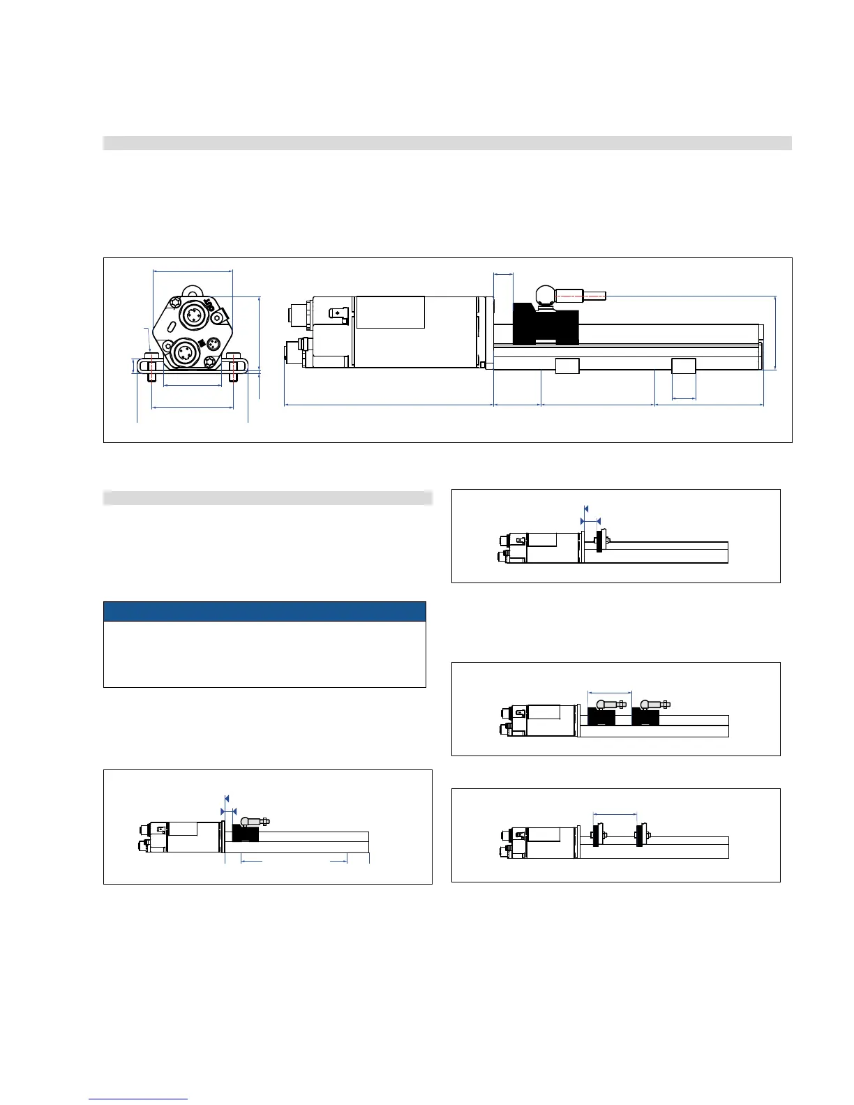
4.2.1 Mounting distances
Active measuring range
The technical data of each sensor is checked as well as documented
and the active stroke length (useful electrical stroke) with its start
and end position is adjusted during final inspection and testing
(see Fig. 2).
NOTICE
On all sensors, the areas left and right of the active stroke length
are provided for mounting and damping of the measuring signal.
They should not be used for measurement, but the active stroke
length can be exceeded without problem.
Mechanical zero
To ensure that the entire measuring range can be used electrically,
the position magnet must be mounted mechanically as follows:
Multi-position measurement
The minimum distance between the magnets is 75 mm (3 in.).
Fig. 3: Temposonics
®
profile with magnet slider
Fig. 2: RP Style dimensional drawing
Fig. 4: Temposonics
®
profile with U-magnet
Fig. 5: Minimum distance for multi position measurement with magnet slider
Fig. 6: Temposonics
®
profile with U-magnet
Controlling design dimensions are always in metric unitsand measurements in ( ) are in inches
12
(0.47)
Start position
Magnet slider

 Loading...


